Dr. N. Subramanian Ph.D., FNAE
Gaithersburg, Maryland, USA
Concrete is not an elastic material, that is, it will not recover its original shape on unloading. In addition, the stress-strain curve of concrete is non-linear. Hence, modulus of elasticity and Poisson’s ratio, which are elastic constants, are not applicable. However, for the sake of simplicity, they are used in the analysis and design of concrete structures, assuming elastic behavior. The modulus of elasticity of concrete is required for the estimation of the deformation of buildings and members. In addition, it is used for determining the modular ratio,m. High-strength concrete (HSC) will have a higher modulus of elasticity and hence will result in reduced deflection and increased tensile strength.
The modulus of elasticity is dependent on the compressive strength of concrete, properties of the coarse aggregates, the proportion of the aggregates in the concrete, quality of cement paste and addition of mineral admixtures (Zhang and Gjvorv, 1991, Neville, 1996). Modulus of elasticity, however, is affected to a lesser extent by the chemical and mineral admixtures, curing conditions, age of the concrete and the type of cement (Russian Standard SP 52-101:2003). The fine and coarse aggregates generally occupy 60% to 75% of the volume of concrete (70% to 85% by mass) and are stiffer than the concrete paste (Neville, 1996). Hence, their E-value will have a significant effect on the E-value of concrete. The use of dense aggregates such as basalt than limestone, which in turn results in a higher modulus than lightweight aggregates. Specifying the largest practical maximum size of aggregate and a suitable grading may result in higher content of coarse aggregate in a concrete mixture. Such concretes tend to have a higher modulus of elasticity, provided the aggregates used have a high modulus of elasticity (Crouch et al., 2007). However, increasing the coarse aggregate size may result in reduced strength in high-strength concrete mixtures. Increasing the paste content may decrease the void content of concrete, and hence may increase the modulus of elasticity. Increasing the water-cement ratio will reduce the value of modulus of elasticity, similar to its effect on the compressive strength of concrete. A high modulus of elasticity is associated with a higher compressive strength of concrete, although the two are not directly proportional. For example, to increase the modulus of elasticity by 20% it may be necessary to increase the strength by 50%. Aïtcin, 2011 observes that the modulus of elasticity of concrete is as important as the water-cement ratio of the concrete mixture. Fig. 1 shows the various factors that may affect the modulus of elasticity of concrete.
Modulus of elasticity may be determined using an extensometer attached to the compression test specimen as described in IS 516:1959 or ASTM-C469M-14 (Subramanian, 2019). The test set-up for measuring the modulus of elasticity is shown in Fig. 2.
Fig. 1: Factors Affecting Modulus of Concrete
Accurate prediction of modulus of elasticity is important in reinforced and pre-stressed concrete structures while calculating member deformations, elastic shortening of columns, shrinkage and creep loss as well as crack width. Note that restricting the crack width is directly related to the durability of concrete structures. The modulus of elasticity is also required in seismic analysis for rational calculation of drift and deformations.
Modulus Of Elasticity Of Concrete
The modulus of elasticity of concrete is defined as the ratio of normal stress to corresponding strain for tensile or compressive stresses below the proportional limit of the material. When the loading is of low intensity and short duration, the initial portion of the stress-strain curve of concrete in compression is linear, justifying the use of modulus of elasticity. When there is sustained load, however, the stress-strain curve will become nonlinear, even at relatively low stresses, due to inelastic creep. Moreover, the effects of creep and shrinkage will make the concrete behave in a non-linear manner. Hence, the initial tangent modulus is considered to be a measure of the dynamic modulus of elasticity (Neville and Brooks 2010).
When the linear elastic analysis is used, one should use the static modulus of elasticity. Various definitions of modulus of elasticity are available: initial tangent modulus, tangent modulus (at a specified stress level), and secant modulus (at a specified stress level), as shown in Fig. 3. Among these, the secant modulus, which is the slope of a line drawn from the origin to the point on the stress-strain curve corresponding to 40% of the failure stress, is considered the average value of Ec under service load conditions (Neville and Brooks 2010).
Fig. 2: Test set-up for Measuring the Modulus of Elasticity of Concrete
Expressions Suggested By Different Codes
Different national codes suggest different expressions for the determination of the modulus of elasticity of concrete, to be used in the design. These expressions are given below.
For normal-weight concrete, Clause 19.2.2.1 of ACI 318M-19 code allows it to be taken as
Where is the cylinder compressive strength of concrete in MPa.
Clause 8.6.2.3 of the Canadian code CSA A23.3-14 gives a similar expression, for normal density concrete with a compressive strength between 20 and 40 MPa as
Clause 6.2.3.1 of IS 456: 2000 suggests that the short-term static modulus of elasticity of concrete, Ec, may be taken as
Where is the cube compressive strength of concrete in MPa.
Both IS 456 and ACI 318 caution that the actual measured values may differ by about 20 % from the values obtained from Eq. (1). Moreover, the US code value is 16% less than the value specified by the Indian code. It has to be noted that the use of a lower value of Ec will result in a conservative (higher) estimate of the short-term elastic deflection.
For both normal-strength (NSC) and high-strength (HSC) concrete, the Comité Euro-International du Béton and the Fédération Internationale de la Précontrainte (CEB-FIP) Model Code and Euro code 2 suggest that the approximate value of secant modulus Ecm of concrete with quartzite aggregates can be obtained from the mean compressive strength as below
Where = + 8 MPa, and is the cylinder compressive strength of concrete The coefficient α present only in the CEB-FIP Model code has a value of 1.2 for basalt and dense limestone, 1.0 for quartzite, 0.9 for limestone, and 0.7 for sandstone aggregates. When lightweight aggregates are used, the CEB-FIP equation was found to overestimates the modulus, and the calculated values decreased when coarse aggregate such as crushed quartzite, crushed limestone, and calcined bauxite was used (Vakhshouri and Nejadi, 2019).
Fig. 3: Various Definitions of Modulus of Elasticity of Concrete
Effect Of Unit Weight Of Concrete On The Modulus Of Elasticity
There is an increased awareness and use of lightweight concrete (LWC) in applications like elevated slab structures; bridge decks; wall, ceiling, and floor insulation; and insulation for fire protection. LWC normally has an in-place density of 800 to 2240 kg/m3. It is traditionally produced using lightweight aggregates such as expanded shale or clay, vermiculite, pumice, or scoria; however, it can be also produced using foaming technologies and polystyrene beads. Only a few codes provide formulae for the modulus of elasticity considering the density of concrete.
Clause 19.2.2.1 of ACI 318:2019 and also the AASHTO-LFRD-2006, provide the following formula for the modulus of elasticity, considering the density (unit weight) of concrete
where ρc is the unit weight of concrete (varies between 1440 kg/m3 and 2560 kg/m3).
As per clause 8.6.2.2 of the Canadian code, the modulus of elasticity, Ec for concrete with ρc between 1500 and 2500 kg/m3 may be taken as
where ρc is the unit weight of concrete.
The Australian code AS 3600:2018, clause 3.1.2 specifies that the modulus of elasticity be taken as below noting that this value may have a range of ± 20%
Where, is the mean value of the in-situ compressive strength of concrete at the relevant age.
Table 3.1.2 of AS 3600:2018 gives the values of Ec calculated as per Eqn. (7) and is shown in Table 1.
The Architectural Institute of Japan specifies the following equation to estimate the modulus of elasticity of concrete
8.
As per BS 8110-2, 1985, the elastic modulus is related to its compressive strength as below
The equation for elastic modulus in the Russian SP 52-101-2003 has a different format as shown below:
High Strength Concrete
High-strength concrete (HSC) is often used in the columns of high-rise buildings, long-span bridges, parking garages, and offshore structures, where improved density, lower permeability, and increased resistance to freeze-thaw and corrosion are required. In these applications, designers can take full advantage of the increased compressive strength of HSC to reduce the amount of steel, reduce column size (to increase usable floor space in high-rise buildings), or allow additional stories. These benefits overshadow the higher cost of raw materials and increased quality control costs involved with HSC.
The ACI committee report on HSC (ACI 363R-92) provides the following equation for modulus of elasticity, which has also been adopted by NZS 3101- Part 1:2006.
The results of the above equation and also Eq. (1) of ACI 318-19, with the experimental values of several researchers, are compared in Fig. 4. It is seen that the ACI 318-19 expression overestimates the modulus of elasticity for concretes with compressive strengths over 41 MPa, and the Eqn. (11) provides better correlation, especially for high-strength concrete.
Fig.4: Modulus of Elasticity Versus Concrete Strength
Clause 3.1.2 of the Australian code AS 3600:2018, suggest the following equation, noting that this value may have a range of ± 20%
The Japanese code JSCE (2007) Clause 4.1.2 [equation C4.1.3] gives the following equation,
Where Ec(t) is the effective Young’s modulus at the age of t days; ф(t) is the compensating factor taking account of creep during concrete temperature increasing for up to 3 days ф =0.73, for after 5 days ф =1.0 (linear interpolation can be used from 3 to 5 days) and (t) is the estimated compressive strength of concrete at t days.
The equations given in the various codes are simple to use because they require only the compressive strength and the concrete density to determine the value of the elastic modulus of concrete. Vakhshouri and Nejadi, 2019 have collated and presented the various other empirical models suggested by other researchers to predict the elastic modulus of normal strength concrete.
Swamy, 1985 showed that the elastic modulus for high strength concrete did not increase in proportion to its strength and the maximum value of modulus will be in the range of 45 to 50 GPa only.
Effect of Different Types of Aggregates of the Elastic Modulus
The equations discussed till now may not be accurate for concrete with all types of aggregates. It is because the elastic modulus and the compressive strength are influenced by several other factors, such as the type of aggregate, humidity, age of the concrete, and the type of binder used. As per Eurocode 2, the value of elastic modulus Ecm as computed by using equation (4), should be reduced for concrete with limestone and sandstone aggregates by 10% and 30% respectively. For basalt aggregates, the value should be increased by 20%. Though not mentioned in the Eurocode 2, equation (4) for concrete with quartzite aggregates is also valid for concrete with siliceous aggregates (Bamforth, et al., 2008). The value of the elastic modulus, for various values of cylinder compressive strength and for different aggregates, as per Eurocode 2, is shown in Fig. 5.
Fig. 5: Modulus of Elasticity of Concrete with Different Aggregates related to the Compressive Strength of Concrete
Only when very high strength concrete is used, the type of aggregate will be known to the designer and hence can be used to predict the value of elastic modulus as per Fig.5. In the case of normal strength concrete, the designer will not know the type of aggregate used, until the concrete supplier is selected. Hence they should exercise caution while using the value of elastic modulus as per Fig.5.
Bamforth, et al., 2008 also recommend testing concrete specimens when the elastic modulus is critical for the performance of any structure. They also suggest adopting the following while designing structures:
Use the mean value of Ecm for serviceability calculations
Use a partial safety factor of γcE of 2, to get the design value of elastic modulus, Ecd = Ecm /γcE and use it in ultimate limit state calculations
Use an effective modulus, Ec,eff =Ecm / (1+ф), where where ф is the creep coefficient, to take care of creep in long-term deflection calculations. The value of the creep coefficient, ф, may range between 1 and 3 (See Bamforth, et , 2008).
Noguchi and Tomosawa, 1995 and Noguchi, et al., 2009 proposed the following equation which applies to a wide range of aggregates and mineral admixtures used in concrete.
(a).
where the correction factors k1 and k2 are given in Tables 2 and 3.
Substituting k1 = 1.0 and k2 = 1.0 and simplifying we get .
14(b).
Fig. 6 shows the variation of strength and modulus of elasticity of concrete, made with different aggregates, calculated as per Eurocode 2 (Bamforth et al., 2008).
The dashed lines in Fig. 6 represent the values calculated by Bamforth et al., 1997 based on aggregate E-value and concrete strength for concrete used in nuclear Power Station Structures.
Fig. 6: Variation of Strength and Modulus of Elasticity of Concrete with Different Aggregates
A comparison of different formulae for the static elastic modulus of concrete is provided in Fig. 7. From Fig. 7 it is also seen that the values calculated as per Euro code 2 expression (Eqn. 4) provide the upper bound and those calculated using Noguchi, et al. (2009) (Eqn. 14) provide the lower bound values. As Eqn. 14 considers a wide range of aggregates and mineral admixtures used in concrete and also gives lower bound values, it is suggested to be included in the future versions of IS 456, instead of Eqn. 3, which considers only the compressive strength of concrete.
Fig. 7: Comparison of Different Formulae for the Static Elastic Modulus of Concrete
Variation Of Modulus Of Elasticity With Time
The value of modulus of elasticity varies with time (Singh et al., 2013). As per Clause 3.1.3(c) of Euro code 2, this time-dependent value of Ec(t) can be determined using the following expression
15(a).
Where Ec(t) and fc(t) are the modulus of elasticity and mean compressive strength ofconcrete at time t and Ec and fc aretherespective values determined at an age of 28 days. The value of fc(t) can be determined using the following expression given in the Euro code 2
15(b).
Where ‘s’ is a coefficient that depends on the type of cement and equals 0.20 for high early strength cement (Class R), 0.25 for normal early strength cement (Class N), and 0.38 for slow early strength cement (Class S).
As the cement class will not be known at the design stage, Bamforth, et al., 2008 recommend assuming Class R and suggest that Class N can be assumed when the quantity of ground-granulated blast-furnace slag (GGBS) exceeds 35% or fly ash exceeds 20% in the cement. Similarly, when GGBS exceeds 65% or fly ash exceeds 35% in the cement, Class S may be assumed. It is important to note the strength gain of cement after 28 days is more dependent on the cement type than the cement strength class. Euro code 2 also warns that Eqn. (15) should not be used retrospectively to justify nonconforming reference strength.
Dynamic Modulus Of Elasticity
The dynamic modulus of elasticity of concrete, Ecd can be determined by the non-destructive electro-dynamic method, by measuring the natural frequency of the fundamental mode of longitudinal vibration of concrete prisms, as described in IS 516:1959. The dynamic modulus of elasticity has to be used in structures subjected to dynamic loading (i.e., impact or earthquake). The value of Ecd is generally 20%, 30%, and 40% higher than the secant modulus for high, medium- and low-strength concretes, respectively (Mehta and Monteiro 2006). More details about the dynamic modulus of elasticity may be found from Popovics, 2008.
Summary And Conclusions
The modulus of elasticity of concrete is required for the estimation of the deformation of buildings and members. The modulus of elasticity is dependent on the compressive strength of concrete, properties of the coarse aggregates, the proportion of the aggregates in the concrete, quality of cement paste, and addition of mineral admixtures. Accurate prediction of modulus of elasticity is important in reinforced and prestressed concrete structures while calculating member deformations, elastic shortening of columns, shrinkage and creep loss as well as crack width. Under normal conditions, the static modulus is specified, which is usually the secant modulus (slope of a line drawn from the origin to the point on the stress-strain curve corresponding to 40 % of the failure stress). The formulae specified in different codes are reviewed. It is seen that several codes consider only the strength of concrete to evaluate the elastic modulus, though a few consider the density of concrete, as well. A few researchers have recommended a formula that considers the effect of a wide range of aggregates and mineral admixtures. It is important for the Indian code, IS 456, to specify a formula, which considers the effect of as many factors as possible, in the evaluation of the elastic modulus of concrete, so that the deformations of structures are predicted accurately.
Acknowledgment
The author wishes to thank Dr. Ahmad Fayeq Ghowsi, Post-Doctoral Fellow at IIT, Delhi, for his help in making the drawings.
References
Interim bridge design specifications and commentary. American Association of Highway and Transportation Officials Washington (DC), 2006
ACI 318:2019 Building code requirements for Structural Concrete and Commentary, American Concrete Institute, Farmington Hills, 628.
ACI 363R-10 2010, State-of-the-art Report on High-strength Concrete, American Concrete Institute, Farmington Hills, 65.
AIJ Standard for Structural Calculations of Reinforced Concrete Structures, Chapter 2, Architectural Institute of Japan, Japan, 1985, 8-11.
Aïtcin P (2011) High performance concrete, CRC Press, Boca Raton, Fl.
AS-3600-18. Australian Concrete structures, Standards Australia, 2018, Australia, pp.45.
Bamforth, , Chisholm, D., Gibbs, J. and Harrison, T. (2008). Properties of Concrete for use in Eurocode 2, The Concrete Center Publication No. CCIP-029, U.K., 53 pp.
Bamforth, , Price, W.F., and Fleischer, C. C. (1997). “The late-life, insitu properties of Concrete in Nuclear Power Station Structures”, Nuclear Energy, Vol. 36, No.2, Apr., pp.149-160.
Comité Euro-International du Béton, “High-Performance Concrete, Recommended Extensions to the Model Code 90—Research Needs,” CEB Bulletin d’Information, 228, 1995, 46 pp.
Crouch, , Pitt, J. and Hewitt R. (2007) “Aggregate Effects on Pervious Portland Cement Concrete Static Modulus of Elasticity”, Journal of Materials in Civil Engineering, 2007, Vol. 19, No.7, pp. 561–568.
CSA A23.3-04 Design of Concrete Structures; Canadian Standards Association: Rexdale, ON, Canada,
ENV 1992-1-1, Eurocode Design of Concrete Structures—Part 1: General Rules and Rules for Buildings, 2004, 225 pp
IS 456:2000 Indian Standard Code of Practice for Plain and Reinforced Cement Concrete,4th revision, Bureau of Indian Standards, New Delhi, 100.
IS 516:1959 (reaffirmed 2018), Method of Tests for Strength of Concrete, Bureau of Indian Standards, New
JSCE (2007). Guidelines for concrete 15, standard specifications for concretestructures- Design. Japan Society of Civil Engineering, Japan, 503 pp.
Jurowski, K., and Grzeszczyk, S. (2018) Influence of Selected Factors on the Relationship between the Dynamic Elastic Modulus and Compressive Strength of Concrete, Materials, Vol.11, No.4, Apr., Doi: 10.3390/ma11040477
Mehta, K., and Monteiro, P. J. M. (2006) Concrete: Microstructure, Properties, and Materials, 3rd edition, McGraw-Hill, New York, p. 659.
Neville, M., Properties of Concrete, 4th Edition, 1996, John Wiley & Sons, New York, 844 pp.
Neville, M. and J.J. Brooks (2010) Concrete Technology, 2nd Edition, Pearson Education Canada, 464pp.
Noguchi, and Tomosawa, F. (1995). “Relationship between compressive strength and modulus of elasticity of high strength concrete.” Journal of Structural and Construction Engineering, (474), pp.1-10. (in Japanese)
Noguchi, , Tomosawa, F., Nemati, K.M., Chiaia, B.M., and Fantilli, A.P. (2009) “A Practical Equation for Elastic Modulus of Concrete”, ACI Structural Journal, Vol.106, No.5, pp. 690-696.
NZS 3101- Part 1:2006, The Design of Concrete Structures, Part 2: Commentary, Standards, Wellington, New
Popovics, (2008). A Study of Static and Dynamic Modulus of Elasticity of Concrete, Final Report, American Concrete Institute – Concrete Research Council, Urbana, IL., 16 pp.
Singh, P. Yazdani, N., and Ramirez (2013) “Effect of Time-dependent Concrete Modulus of Elasticity on Prestress Losses in Bridge Girders”, International Journal of Concrete Structures and Materials, Vol. 7, pp. 183-191.
SP-52-101-2003. Concrete and Reinforced Concrete Structures Without Prestressing, Gosstroi, Russia, Moscow, 2004, 55
Subramanian, N. (2019). Building Materials, Testing, and Sustainability, Oxford University Press, New Delhi, 788
Swamy, N. (1985) “High-Strength Concrete-Material Properties and Behavior”,ACI SP87-8, pp. 119–145
Topcu, B., and Ugurlu, A. (2007), “Elasticity Theory of Concrete and Prediction of Static E-modulus for Dam Concrete using Composite Models”, Teknik Dergi, Vol.18, No.1, pp. 4055-4067.
Vakhshouri, , and Nejadi, S. (2019) “Empirical Models and Design Codes in Prediction of Modulus of Elasticity of Concrete”, Frontiers of Structural and Civil Engineering, Vol. 13, pp. 38–48.
Zhang, H and Gjvorv, O. E. (1991) “Mechanical Properties of High-Strength Lightweight Concrete”, Materials Journal, Vol. 88, No.3, pp. 240–247.
Shridhar A. Behare Associate Professor & Head Department of Civil Engineering, Shreeyash College of Engineering Aurangabad
When considering durability of concrete, chloride attack is the most imminent enemy. In the presence of oxygen and water, chloride attack corrodes the steel reducing the strength of the structure drastically.
Chloride ion (Cl-) is formed when the element chlorine gains an electron or when a compound such as hydrogen chloride is dissolved in water. High concentrations of chloride ions in concrete, due to their electro-chemical nature, break down the passive layer of reinforcing steel, without the need to drop the pH levels. Corrosion takes place as the chloride ions react with steel and the surrounding passive material to produce a chemical process which forms hydrochloric acid. The hydrochloric acid reacts with the steel reinforcement, whereby the volume of steel is increased due to corrosion leading to concrete cracking, spalling and eventually failure of concrete.
There are two main sources of chloride ions, one is from the concrete making materials, and the other from the surrounding environment. The first could come from aggregates, admixtures, and from water used for making concrete and the second comes mainly from the concrete being exposed to marine environment such as sea salt spray, direct seawater wetting, concrete being in contact with soils that are rich with chlorides deposits or it can come from de-icing salts and use of chemicals. It is by the process of diffusion that chloride penetrates the concrete. The main problem involving the corrosion of the steel is the spalling of the concrete cover. The oxide resulting from the corrosion is very porous and takes up to 10 times the volume of the steel which causes the break-up of the concrete.
RCPT Test
The Rapid Chloride Permeability Test (RCPT) is a test that uses the total charge, driven by an applied electric field of 60 Volts, passing through a 2-inch thick and 4-inch diameter concrete sample over a period of 6 hours, as an index of the concrete permeability. This test has been standardized as ASTM C 1202/AASHTO T 277. The specimens are vacuum-saturated with de-aired water before testing. An electrical current is conducted from the power source by placing one end of the sample in a 0.3 N NaOH solution and the other end in a 3.0% NaCl solution. Although the test is intended as an indirect measure of the concrete pore system network, anything that changes the concrete resistivity will change the results. For example, certain admixtures such as calcium nitrite change the pore solution conductivity and change the results. Likewise, conductive fibers or aggregates that contain hematite can change the concrete electrical resistivity without changing diffusion properties. Changes in the vacuum pressure used during saturation or other specimen conditioning prior to testing can also change the sample resistivity due to the effect of the degree of saturation of the tested specimen on the measured result.
RCMT Test
The Rapid Chloride Migration Test (RCMT, NT Build 492) uses electrical voltage to accelerate chloride migration. The test specimen shall be 4 inches in diameter and 2 inches thick, and prior testing the specimen is vacuum-impregnated with saturated lime solution as described in NT Build 492. After the specimen is prepared, the concrete is exposed to a 10% NaCl solution on one side and a 0.3 N NaOH solution on the other. The test starts by measuring the initial current through the sample for an applied 30 volts.
Fig. 1: Schematic RCMT Set Up
The initial and final current through the specimen and specimen temperature are measured. After the test duration is completed, the concrete specimen is split open and a 0.1M silver nitrate reagent is applied to the sample. The chloride penetration depth, as evidenced by the precipitation on the specimen of silver chloride, is measured at least seven depths to an accuracy of 0.1mm (0.0039 inch). The surface chloride content can optionally be measured by cutting a 5mm (0.197 inch) concrete slice on the surface exposed to the chloride solution and measuring the acid-soluble chloride content in the slice. This chloride content can be used to get information on the concrete sample chloride binding capacity.
Use Of Secondary/Supplementary Cementitious Materials (SCMs)
The addition of SCMs to concrete can substantially increase the concrete’s resistance to chloride ingress. The use of SCMs can improve concrete’s durability, resistance to degradation due to multiple mechanisms, and strength gain behaviour. SCMs have two primary forms of reaction that influence the properties of the concrete. The hydration and chemical reactivity of SCMs are functions of their compositions, with many SCMs showing varying ranges of each type of reactivity.
Latent Hydraulic Reactivity
The material will react with water to form strength-bearing phases, with or without the presence of Portland cement. SCMs of this form typically will contain both calcium and reactive silicates.
Pozzolanic Reactivity
The SCMs will react chemically with water and the hydrated cement paste to form additional strength-bearing phases and cause a densification of the microstructure. Pozzolanic materials are typically siliceous in nature and need not contain lime-bearing phases. The reaction rates of SCMs impact their influence on the pore structure, and as a result reducing the rate of chloride diffusion through concrete. For the purpose of this study, the following materials were used in concrete and the test results evaluated to study the chloride migration characteristics of concrete:
Ground Granulated Blast Furnace Slag (GGBS)
Fly Ash
Alccofine 1203
Ground Granulated Blast Furnace Slag (GGBS): Ground granulated blast-furnace slag, is a by-product of steel production. Slag is primarily composed of CaO, SiO2, aluminum oxide (Al2O3), and magnesium oxide (MgO). When used as part of a Portland cement concrete, slag reacts with both the water (latent hydraulic reaction) and the hydrated cement paste (Pozzolanic reaction), resulting in a more refined microstructure than that of a plain Portland cement.
Fly Ash: Fly ash is a by-product of coal combustion and composed primarily of silicon dioxide (SiO2) and calcium oxide (CaO). When added to concrete, fly ash reacts with the hydrated cement paste in a primarily Pozzolanic reaction; the result is a denser microstructure over time.
Alccofine 1203: Alccofine 1203 is a new generation, ultrafine, low calcium silicate product manufactured by Counto Microfine Products Pvt. Ltd. (CMPPL) – a joint venture between Ambuja Cement Limited & Goa based, Alcon group. The production facility is at Pissurlem Industrial Estate.
Concrete Mix Design
Concrete trials were conducted with the following proportions: a). OPC alone.
OPC + Fly Ash, replacing 20%, 35% , 40% & 60% of Fly Ash in cementitious
OPC + GGBS, with replacing 35%, 50%, 70% & 90% of GGBS in cementitious
OPC + Alccofine 1203, with replacing of 5%, 15%, 25% & 35% of Alccofine 1203 incementitious
OPC + Fly Ash + 5% Alccofine 1203, replacing 20%, 35%, 40% & 60% of Fly Ash in cementitious
OPC + GGBS + 5% Alccofine 1203, with replacing 35%, 50%, 70%& 90% of GGBS in cementitious
OPC + Fly Ash + 3% Alccofine 1203, replacing 20%, 35%, 40% & 60% of Fly Ash in cementitious
OPC + GGBS + Alccofine 1203, with replacing 35%, 50%, 70% & 90% of GGBS in cementitious
The Test Method
The test method used to find the chloride ingress resistance of the concrete was the NT Build 492 test. The NT Build 492 test comes from the Nord Test (Based in Finland) family of test methods. This is an alternative to ASTMC1202, and the result is a chloride migration coefficient from non-steady state migration experiment, DNSSM x10¯12m2/sec, that can be used to access the quality of concrete. NT Build 492 is adopted widely in Europe and the USA. It is also fully adopted in China, as the National Standard GB/T50476. Apart from the above some experiments were also conducted by using the ASTM C1202 test method, with the mix proportion given in the Table 1 for Sr. No. 18 to Sr. No. 29, the results of the tests are presented in figure 5.
Difference Between ASTM C1202 Method And NT Build492
The NT Build 492“Chloride Migration Coefficient from Non- Steady State Migration Experiments” (RCMT) test method is different from the widely used ASTM C1202 test, the ASTM C1202 test is often criticized based on a report from a FHWA (Federal Highway Administration, U.S. Department of Transportation) study by Whiting[1].
The fundamental differences between the NT Build 492 “Chloride Migration Coefficient from Non- Steady Sate Migration Experiments” and the ASTM C1202 “Standard Test Method for Electrical Indication of Concrete’s Ability to Resist Chloride Ion Penetration” (RCPT) test method are:
RCPT test fundamentally is simply a conductivity test or inverse- resistivity test and in spite of it often being referred to as Rapid Chloride Permeability Test, it does not measure the “permeability” or “chloride diffusion” of concrete[2].
High current flow in RCPT test results in heating of the sample and solution during the 6 hours test, raising the measured conductivity, thus a better quality concrete looks worse than it would
The transport of ions in concrete depends on the pore structure of the concrete, while the electrical conductivity of concrete or RCPT results depend upon both pore structure and electrical conductivity of the pore solution, which in turn is determined by composition of the pore
It is not correct to use electrical conductivity of concrete or RCPT results to rank rapid chloride permeability of concrete containing supplementary cementitious materials[4].
ASTM C1202 states in clause 1, that this test method is applicable to types of concrete where correlations have been established between this test procedure and long term chloride ponding procedures such as those described in AASHTO T 259. In other words, establishing correlation with the ponding test is a prerequisite for using RCPT. How many laboratories actually conduct the classical 90-day soaking test and establish the correlation with RCPT, is not known.
High water reducing admixtures work on the principle of electrical polarity to create electrical This may cause substantial changes to the overall electrical conductivity of concrete. It has been reported that different types of water reducing agents added to otherwise identical concrete mixes caused variance of up to 700 coulombs in total charge passed in RCPT.[9]
On Precision and Bias, ASTM C1202 states that the single operator coefficient of variation of a single test result has been found to be 12.3%. The variability of results between two properly conducted tests by the same operator could be as much as 42%. The multi laboratory coefficient of variation of a single test has been found to be 18.0%. Therefore, results of two properly conducted tests in different laboratories could varyby as much as 51%.
RCMT test is a non-steady state migration test, developed by Tang and Nelson[5]and adopted as NT Build 492 involves measurement of the depth of chloride ingress under applied DC potential (voltage and time of the test are determined from an initial current measurement).
In RCMT for avoiding the influence of other carrying ions, the non-steady state migration coefficient is calculated from the actual chloride ion penetration measured from visible silver chloride precipitation that is developed after application of silver nitrate solution on the axial split specimen on completion of the test.
The results of RCMT are not influenced by concrete pore fluid conductivity and depth of chloride penetration is measured
The calculated diffusion coefficient can be used in service life prediction models[2].
Note:A detailed study on RCPT as per ASTM C 1202 can be found in the article – “Revisiting Rapid Chloride Permeability” by Milind Joshi and Siddika Mapari, POV, ICI 2010.
Brief Description Of Test (NT Build 492)
This test procedure and test conditions can be briefly summarized as follows:
Samples of 100mm in diameter and 50mm in height are
Vacuum-saturation of the samples with limewater performed prior to the
10% (wt.) NaCl solution used as the catholyte and 3M NaOH solution used as the anolyte.
Applied voltage in the range of 10 – 60 V, decided upon the value of the initial current, measured at a voltage of 30
Duration of the test of 6 – 96 h, decided upon the value of the initial current, measured at a voltage of 30
Correction factor of 2 V used in the equation for calculating the DNSSM, accounting for the polarization of the
Temperature during the test between 20 and 25 °C.
Use Of NT Build 492 Test In India
In India awareness about designing concrete structures for durability is slowly increasing, the practice of specifying durability test for qualification of concrete mixes is also increasing at a slow rate. Currently, RCPT tests as per ASTM C1202 is specified for most of the metro rail projects as well as in many roads and bridges in the country, RCPT NT Build has been specified in the Bandra-Worli sea link bridge with limiting factor for pre-qualification of concrete mixes to be <2×10-12m2/sec. Considering technical advantages of the NT Build 492 test method over the ASTM C1202 method and as per the current trends in the industry, NT Build 492 is expected to replace the ASTM C1202 test in the years to come.
Test Results
All the experiments for RCMT were carried out at the R&D Division of Alcon Construction (Goa) Pvt. Ltd., at Goa, where the test facilities of NT Build 492 is available, the test results of the experiments are tabulated in the Table 1 below and the graphical representation are given in Figure 2, 3 & 4.
Fig. 2: RCMT Results at 7, 28 and 56 Days by using Different Proportions of Fly Ash, Alccofine 1203 and GGBS with Different Proportions
Fig. 3: 28 Days and 56 Days RCMT Results of Concrete with 3% of Alccofine 1203 and Fly Ash/GGBS in Varying Proportion
Fig. 4: 28 Days and 56 Days RCMT Results of Concrete with 5% Alccofine 1203 and Fly Ash/ GGBS in Varying Proportions
Fig.5: 7 Days and 56 Days RCPT Results of Concrete with Varying Proportions of Fly Ash, GGBS and Alccofine 1203
Interpretation Of Results
The chloride migration coefficient under non-steady-state (DNSSM) is used for evaluating the concrete resistance to chloride penetration, according to the criteria presented in Table No. 2.
TPlease note that the results presented here are of single test for each different proportions of cementitious content (result is the average of three specimens), according to the results from Nordic round robin test between six laboratories, the coefficient of variation of repeatability of results is 9% and the coefficient of variation of reproducibility of results is 13% for Portland cement or for concrete mixed with silica fume and 24% for concrete mixed with slag [7]. The most effective SCM has been found as GGBS [10].
Conclusion
RCMT value for fly ash concrete is very high at initial ages; the values are reduced at later ages of 28 and 56
All the 56 days RCMT results of concrete with supplementary cementitious materials are less than 2 x 10-12m2/sec which relate to very good resistance to chloride
RCMT values of concrete with only OPC are high and having least resistivity to chloride ingress as per the results of
The results RCMT of OPC + GGBS/OPC + GGBS + Alccofine 1203 combination have the lowest results when compared to OPC + Fly Ash/OPC + Fly Ash + Alccofine 1203 combination, RCPT results in Figure 5 also show similar trends for OPC + GGBS combination.
Addition of secondary/supplementary cementitious materials greatly improves the resistivity of concrete to chloride ingress, due to the improvement of pore structure of the concrete due to formation of additional calcium silicate hydrates in the hardened cement paste, which is able to resist the ingress of corrosion inducing
RCMT values of concrete with 3-5% of Alccofine 1203 are the least of all the combination so far secondary/supplementary cementitious
Highly durable concrete can be obtained by addition of 3-5% of Alccofine 1203 to OPC + GGBS & OPC + Fly Ash concrete.
Concrete containing Alccofine 1203 which is a low calcium silicate based mineral additive is able to achieve the lowest values of chloride diffusion due to its unique particle size distribution resulting in enhanced hydration process, improved packing density of the paste component while lowering the water demand resulting in improved strength and durability of the concrete.
Acknowledgments
RCPT tests were done at Goa Site of Gammon Engineers and Contractors Private Limited, Mumbai under the supervision of Mr Vivekanand
Similarly, RCMT tests were done in Alcon Lab by Mr Siddhesh
Results of both the tests were regularly monitored by Shridhar Behare.
The whole investigations were done under the guidance of Dr V. Nayak.
References
Whiting, , “Rapid Determination of the Chloride Ion Permeability of Concrete,” Final Report No. FHWAJRD-371/1 19. US Federal Highway Administration (1981).
Development and Standardisation of Rapid Methods for Assessing the Fluid Penetration Resistance of Concrete,
Hooton, D., Charmchi, G. and Karkar, E., XII International Conference on Durability of Building Materials and Components (XII DBMC), RILEM Proceeding Pro 96, Sao Paulo, 2-5 September 2014.
Shi Caijun, Another look at the Rapid Chloride Permeability Test (ASTM CI 202 or ASSHTO T277)
Tang, and Nilsson, L.O., “Rapid Determination of Chloride Diffusivity in Concrete by applying an Electrical Field,” ACI Matls. J., 89 (1) (1991)49-53.
Standard test method for electrical indication of concrete’s ability to resist chloride ion phenomenon, ASTM C1202-97, American Society for Testing and Materials,
NT Build 492 “Chloride Migration Coefficient from Non-Steady State Migration
State-of-the-Art Report (Draft), RILEM TC 230 – PSC, RILEM Technical Committee on Performance Specification for Concrete
Krieg, Willfried, Rapid Chloride Permeability Testing- a critical review,
Dr. M. R. Kalgal Technical Advisor
UltraTech Cement Ltd.
Concrete As A Sustainable Material
In the search for materials and systems that will provide a durable foundation for sustainable communities, people are increasingly turning to concrete. When considered over its entire life cycle, concrete makes a significant contribution to the triple bottom line – environmental, social and economic – of sustainable development.
From runways to highways, from subways to transit-ways, concrete helps develop and maintain a sustainable, environmentally-friendly transportation infrastructure. Regardless of the type of roadway or current pavement conditions, there is a concrete solution. Concrete can be used for new pavements, reconstruction, resurfacing, restoration or rehabilitation. Concrete pavements generally provide the longest life, least maintenance, and lowest life-cycle cost of all alternatives. Plus, due to higher bitumen prices, concrete has become the least expensive alternative for even new construction on a first-cost basis.
Making Concrete More Sustainable
Having realized the inevitability of using concrete for developmental works for quite some time to come, efforts are on throughout the world to try and make concrete more sustainable. The approaches can be broadly classified as follows:
1. Make Cement More Sustainable
Use less energy intensive kilns
Use supplementary cementitious materials to reduce clinker component
Use new types of clinker
Use alternative fuels and renewable energy during production process
Produce clinker free cement
2. Use Alternative Materials In Concrete
Alternative cementitious materials
Alternative aggregates
Wastes in Concrete (Converting Liabilities into Assets)
3. Make Concrete More Durable
sustainability through longer lasting structures
4. Capture And Sequester CO2 In Concrete Or Store CO2 In bedrocks
5. Produce Clinker Free Concrete
An effort is made in this paper to look at the work being carried out across the world and the promise these hold towards achieving sustainability targets.
2050 Climate Ambition Of GCCA
Global Cement and Concrete Association (GCCA), is a CEO led industry initiative headquartered in London. It has amongst its members about 40 of the world’s leading cement and concrete companies as well as about 25 affiliates which are cement and concrete associations. GCCA announced the formation of a strategic partnership with the World Business Council for Sustainable Development (WBCSD) to facilitate sustainable development of the cement and concrete sectors and their value chains. The new partnership also created synergies between work program to benefit both the GCCA and WBCSD and their respective member companies. As part of the new agreement, the work carried out by the Cement Sustainability Initiative (CSI) was transferred from WBCSD to the GCCA on 1st January, 2019 with activities managed out of the GCCA’s London offices.
The vision of GCCA sees “a world where concrete supports global sustainable economic, social and environmental development priorities; and where it is valued as an essential material to deliver a sustainable future for the built environment”. GCCA has unveiled the 2050 Climate Ambition on 1st September 2020 which demonstrates the commitment of the industry across the globe to drive down the CO2 footprint of the world’s most used man-made product, with an aspiration to deliver society with carbon neutral concrete by 2050.
The statement identifies the essential levers that will be required to achieving carbon neutral concrete, including:
reducing and eliminating energy related emissions,
reducing process emissions through new technologies and
deployment of carbon capture, more efficient use of concrete, reuse and recycling of concrete and buildings, and harnessing concrete’s ability to absorb and store carbon from the
5C Framework Of Cembureau
Cembureau the European Cement Association based in Brussels is the representative organisation of the cement industry in Europe. It is trying to coordinate the efforts of the cement and concrete industry to play an essential role to help Europe achieve its strategic objectives on growth, innovation, social inclusion and climate and energy. They also have come up with a vision to achieve Carbon Neutral Europe by 2050. It is being attempted through the 5C Framework. The 5 Cs stand for clinker, cement, concrete, construction & built environment, and (re)carbonation.
Clinker
Cembureau recognizes that the circular economy goes hand in hand with carbon neutrality. Circularity is crucial to reduce emissions from clinker, which is the backbone of cement production. Efforts are on world-wide to use nonrecyclable waste to phase-out fossil fuels from cement production. It will become even more crucial tomorrow, as CO2 captured during clinker manufacturing will be used in other industrial applications.
The manufacturing process where raw materials are heated up and decarbonisation of the limestone is a chemical process which causes 60%-65% of cement manufacturing emissions (process emissions). The remainder of CO2 emissions comes from the fuels used to heat the kiln (combustion emissions). Since clinker production represents the lion share of emissions, this is obviously the area that offers most opportunities for deeper CO2 emission cuts.
The graphic given in Fig. 1 very nicely depicts the possible quantum of CO2 reductions by a multi-pronged approach.
Fig. 1: Opportunities to Achieve CO2 Reductions for Clinker (Courtesy Cembureau Website)
Cement
There are no further CO2 emissions at the stage of cement production. However, electricity is used for grinding and mixing, and incoming materials as well as final cement products are transported. Cembureau thus identifies that some cements can be made with less clinker, or even alternatives to clinker, to achieve significant emission savings. In addition, a reliable and affordable supply of renewable energy as well as zero carbon alternatives to diesel for industrial vehicles can further reduce emissions at the cement stage. Fig. 2 depicts the quantum of CO2 reduction at this stage.
Fig. 2: Opportunities to Achieve CO2 Reductions for Cement (Courtesy Cembureau Website)
Concrete
The direct CO2 emissions related to concrete largely come from cement production. The largest indirect CO2 emissions come from transportation of concrete to the end user. Fig. 3 indicates the possibility of reducing the CO2 impact of concrete.
Fig. 3: Opportunities to Achieve CO2 Reductions for Concrete (Courtesy Cembureau Website)
Construction
Concrete which is already ubiquitous offers a working life in excess of 100 years, provides fire resistance, and is able to reduce energy consumption for heating and cooling by 25%. This opens significant opportunities to reduce emissions not only for concrete itself, but for the overall construction sector. Cembureau’s Report lists the following possibilities to achieve reduction of CO2 emissions/impact in constructions:
Energy efficiency in buildings: leverage thermal mass properties of concrete to cut energy used during the working life of buildings.
Concrete used in buildings: reducing embodied carbon by using concrete more efficiently and using advanced techniques like 3D printing, leading to reduction in the quantum of concrete used.
Design for adaptability and disassembly: using concrete structures’ adaptability for mixed use buildings and changing needs as well as exploring the “design for deconstruction” model where building is conceived at origin with the objective to disassemble at the end of life. This approach allows materials and components to be removed easily and to be re-used to construct new buildings.
Re-Carbonation
In addition to reducing emissions, carbon neutrality can also be reached through greenhouse gas emissions removal through carbon sinks, states Cembureau Report. Cement and concrete have here a key role to play through a process called re-carbonation, which effectively transforms the cities into carbon sinks.
Re-carbonation is the process whereby concrete re-absorbs some of the CO2 that was released during clinker production. It is a process that occurs naturally in all concrete structures, permanently trapping the CO2. Thanks to re-carbonation, cities effectively act as carbon sinks, allowing further reduction of emissions in the full cement and concrete value chain.
Cembureau identifies 3 major thrust areas here.
Re-carbonationinthebuiltenvironment: re-carbonation occurs naturally in all concrete infrastructure and it is said that 23% of process CO2 emissions of cement used, is being captured annually, which equates to about 8% saving of total CO2 emissions for the cement manufactured
Enhanced re-carbonation of recycled concrete: it is known that re-carbonation increases after demolition of a concrete building. This can be accelerated by using exhaust gases from a cement kiln (which have higher CO2 content and are also at a higher temperature) increasing the CO2 captured up to 50% of process CO2 emissions. Cembureau Report also suggests separating the aggregates from recycled concrete and grinding the cement paste for higher capture of CO2 and the resulting material can be used as a clinker replacement in cement or as an additive in concrete
Carbonation of natural mineral: it is stated that natural minerals such as basalt and olivine can be re-carbonated by exposing it to air and kiln exhaust gases. Such materials can be used as clinker substitutes.
In summary all the 5C initiatives combined with what is already achieved in terms of reducing CO2 reduction would result in Carbon neutrality in construction sector by 2050 says Cembrureau. This is shown graphically in the Fig. 4.
Other Major Initiatives Around The Globe
Worldwide, hundreds of companies and research groups are working to keep CO2 out of the atmosphere and store it someplace else, including in deep geologic formations, soils, soda bubbles, and concrete blocks. By making waste CO2 into something marketable, entrepreneurs can begin raising revenues needed to scale their technologies. Some of these are given below to indicate the approaches followed.
Fig. 5: Typical Components of LC3
Limestone Calcined Clay Cement (LC3) This new blend substitutes up to half of the usual Portland cement used to make concrete with highly abundant clay and limestone, promising to reduce cement-related CO2 emissions by up to 30%. When used together, the aluminates from the calcined clay interact with the calcium carbonates from the limestone, leading to a less porous, and therefore stronger, cement paste. The efforts towards developing and testing this new blend was initiated by Ecole Polytechnique Federale De Lausanne (EPFL) with funding from Swiss Agency for Development and Cooperation (SDCC) with partners from the Indian Institutes of Technology and from universities in Cuba and Brazil.
The typical components of LC3 are indicated in Fig. 5. The major innovation in LC3 is to combine the use of abundantly available low-grade kaolinite clay with a further 15% of limestone, with no reduction in mechanical performance.
LC3 Vs. LC2 It is possible to produce LC3 by inter-grinding Limestone, Calcined Clay and Clinker or produce LC2 by grinding Limestone and Calcined Clay alone. This LC2 can be mixed with OPC anytime to obtain LC3. The processes are indicated in Fig. 6.
Fig. 6: Production of LC3 and LC2 (Courtesy EPFL)
Benefits of LC3
Reduced Clinker factor reduces CO2
Emissions of LC3are estimated to be 20-30% lower than Portland cement because:
Reduced clinker content leads to less process emissions from the decarbonation of limestone in clinker and less emissions from heating limestone to form
Grinding limestone takes less energy than heating
Calcination of clay takes place at 800°C and uses roughly 55% of the energy needed for clinkerisation at 1450°C.
Kaolinite content needed for LC3is much lower and hence use of such ‘low grade’ clays would not compete with demand for resources by other Use of such resources would neither require opening of new quarries nor deplete agricultural soils. In fact large stockpiles of low grade “waste clays” are seen stockpiled near kaolinite based industries as shown in Fig. 7.
Limestone unsuitable for clinker production can be used. e.g. high dolomite content produces Periclase during clinker production, which causes expansion. Such materials can be utilised safely in interground applications, leading to more efficient use of limestone
Depending on the exact scenario, the amount of cement that can be produced from the same identified limestone reserve could be increased two-fold.
LC3 can be produced with existing manufacturing equipment, leading to only marginally increased investments for calcining equipment.
Fig. 7: Clay Suitable for LC3
CemZero CemZero is a Swedish project by cement manufacturer Cementa and the energy company Vattenfall with the aim of reducing greenhouse gas emissions. The project includes studies of calcination and clinker mineral formation for carbonate based raw materials under electrical heating, carbonation under cooling in high CO2 concentrations, evaluations of technologies aiming at upscaling, and determination of gas composition in the CO2 rich process gases.
The suitability of the gases for capture, transport and geological storage, or other use, will be evaluated. There are 3 major thrust areas of research in this project which is expected to be completed by 2025. The thrust areas are:
Heat transfer with plasma in rotary
Direct separation of CO2 from calcination of carbonate based raw materials in the production of cement clinker and burnt
CO2free products with electrified production-reactivity of cement clinker with secondary
LEILAC
Supported by the European Union, the LEILAC (Low Emissions Intensity Lime And Cement) projects are developing a breakthrough technology that aims toenable the cement andlime industries to capture those unavoidable CO2 emissions emitted from the raw limestone. The LEILAC technology is based on Calix’s Direct Separation technology, which aims to enable the efficient capture of the unavoidable process carbon emissions, derived from its original application in the magnesite industry. In addition to the main technology targets that will be demonstrated, the project scope includes a thorough analysis of the potential destination of the captured CO2, for use in processes, as well as for safe geological storage.
CIMENTALGUE
The CIMENTALGUE project is part of the development of a new ‘industrial symbiosis’combining the cement industry, which produces industrial effluent rich in CO2, NOx, trace elements and unavoidable energy waste, on the one hand and the emerging microalgae cultivation industry, which consumes CO2, nitrogen, trace elements and heat, on the other.
CIMENTALGUE is aimed at developing a process for exploiting CO2 and unavoidable heat waste from industrial sources by producing photosynthetic microalgae in natural light in photobioreactors under glass.
The project will install a 500m² demonstrator micro algae production unit inside a cement works. This installation will be operated for two and a half years to provide representative data for the entire value chain from capture and treatment of industrial waste gas to developing the economic potential of the microalgae biomass produced.
The project will perfect and optimise its process, prove its sustainability and ensure its economic and environmental validation in terms of norms, social acceptance and profitability on target markets (as additives for animal feed, dyes, materials, etc.)
CarbonCureTM Technologies
CarbonCure Technologies, from Canada, has demonstrated a technology which enables the production of concrete with a reduced water and carbon footprint without sacrifice to the material’s reliability. CarbonCure Technologies offers a technology to implement carbon dioxide (CO2) utilization in the ready mix concrete industry. Using this technology, waste CO2 can be put to a beneficial use as a feedstock in the production of concrete. The retrofit CarbonCure TM Ready Mix Technology adds CO2 to concrete during mixing. The CO2 reacts with the cement and is mineralized to produce nanoscale calcium carbonate. The carbonate formation can impart positive impacts on the concrete. The CO2 addition (hereafter, CarbonCure)can improve hydration and increase compressive strength without affecting the fresh concrete properties.
Utilizing CarbonCure Technologies’ system, a precise dosage of CO2 is injected into a concrete plant’s reclaimer system, which contains the water used to wash out concrete trucks and mixers. The CO2 is converted to a permanently embedded mineral with strength-enhancing properties which can then be incorporated into new concrete mixes. By reducing the amount of new freshwater, solid waste disposal and cement required, the team, which is backed by Bill Gates’ fund Breakthrough Energy Ventures, Amazon Climate Pledge Fund, BDC Capital and others, is able to reduce the material costs and increase profitability for concrete producers.
CarbonCure has a recommended dosage rate of 50 – 250g/100kg of cement (as distinct from total cementitious) for most applications. Dosages outside this range may be used if local testing shows acceptable performance. Pre-testing is required to determine the appropriate addition rate for desired performance. The optimum addition rate may be influenced by other concrete mixture components, cement types, ambient temperature, mineral additives, quality and gradations of aggregates, slump of concrete, mixing equipment, job conditions and desired performance characteristics. The optimum performance of the CarbonCure is said to be generally obtained with a delayed addition following the start of mixing. Packaging and handling CO2 is available in bulk and delivered by tanker truck to an on-site pressurized storage tank for dispensing by means of the CO2 metering equipment. CO2 must have a certified purity of 99% or above for use in this application. The dispensing control system is connected to the batching system and the CO2 addition is fully integrated into the batch sequencing of materials that are added to the mix.
CarbonBuilt™
CarbonBuilt’s core technology emerged out of the Institute for Carbon Management at the University of California, Los Angeles (UCLA). The CO2 Concrete process developed by University of California directly converts carbon dioxide from power plants or other emitters into precast concrete and concrete masonry products (such as blocks and beams) that can be used for construction worldwide. This direct conversion bypasses any need for CO2 purification or enrichment that is endemic to nearly all other methods for absorbing CO2 smokestack emissions into concrete. The widespread adoption and use of conventional concrete by CO2 Concrete would dramatically cut CO2 emissions resulting from the production of cement. Due to its novel chemistry, CO2 Concrete achieves unprecedented levels of CO2 uptake, resulting in a carbon intensity (CI) that is up to 65% lower than that of conventional concrete.
CarbonBuilt’s Reversa™ technology is a low-cost solution for thermal energy, cement, steel or incineration operators seeking to beneficially utilize their waste CO₂, ash or slag. Their modular technology can be added to a site to permanently embed flue gas CO₂ into masonry or precast concrete produced nearby. CarbonBuilt’s Reversa™ process includes CO₂ emission-reducing innovations to both the concrete mix design and its curing process. On the formulation side, they introduce portlandite (also known as calcium hydroxide, a commodity chemical), reduce the usage of traditional cement and increase the use of waste materials like fly ash. The concrete is then formed using the same processes and equipment that are used today.
Fig. 8: CarbonBuilt’s Reversa™ Technology
After forming, we cure the concrete with waste CO₂ emissions using a process that does not require expensive capture, compression or purification of the CO₂.
The Reversa process reduces emissions through a combination of utilization (permanently embedding CO₂ into the concrete) and avoidance (reducing CO₂ emissions associated with the raw materials).
The process requires minimal CAPEX, since it features simple “stack-tap” integration with limited site utility tie-ins, does not require a carbon capture system, and readily integrates into existing construction supply chains and workflows. Their approach can also make greater and more flexible use of fly ash, slag or other supplementary cementitious materials than is possible with conventional concrete while providing engineering performance equivalent to typical concrete. The low cost of this technology is a significant advantage in the low margin concrete business.
Carbonated Calcium Silicate Concrete
It is a patented process from USA based Solidia Technologies. It is a low-lime calcium silicate (Ca2SiO4) cement (CSC) that cures by a reaction with gaseous carbon dioxide (CO2). The production of CSC requires less limestone and lower kiln temperatures than those used for ordinary Portland cement (OPC). This makes it possible to reduce the carbon dioxide emissions at the cement kiln from ~810 kg/t for OPC to ~565 kg/t for CSC. The carbon dioxide used in the curing process and captured within CSC-based concrete (CSC-C) is industrial- grade carbon dioxide sourced from waste flue gas streams. These translate to approximately 30% reduction in CO2 emissions.
ZERO Clinker Cement
Hoffmann Green Cement Technologies is a French company involved with production of Geopolymer (Zero Clinker) products. Majorly they have 3 products:
HP2A (High Performance Alkaline Activation) cement: It is a 100% mineral, non-flammable and VOC -free adhesive based on activated clay and silicate in the form of a two-component“paste & liquid”system. Activators and super-activators formulated are added to flashed clay mixed with silicate to obtain H-P2A cement. It is said to have pull-out strength of more than 25 MPa.
H-UKR cement: This is a solution based on the use of blast furnace slag. Efficient activation system allows this co-product to be used without any addition of clinker in its formulation. It can be used in various fields of construction, including ready-mix concrete and precast concrete.
H-EVA cement: It is an innovative binder, based on an alkaline ettringitic technology. Activators and super-activators formulated are added to flashed clay, mixed with gypsum/desulfogypsum to obtain H-EVA cement. It is said to have strength of up to 60 MPa at 28 days. It is said to be ideal as a road binder, but can also be used for mortars, plasters and construction concretes.
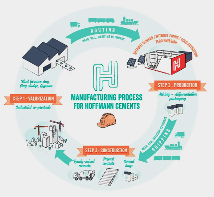
Fig. 9: Production of Zero Clinker Cement
The manufacture involves the following steps –
Step 1: Valorization (Conferring Value Upon Something)
Recover and enhance co-products from industry and construction, which are sent to production plant. Blast furnace slag comes from the metallurgical and steel industry, Flash clay is a co-product of clay sludge and Gypsum/Desulfogypsum are produced from construction site excavated material.
Step 2: Production
The manufacturing process is based on the systematic use of abundant co-products as a substitute for natural resources. The co-products, are mixed with activators and super-activators specifically formulated. This is followed by the packaging of cements (big bag, bulk or bags) and then shipment to the construction sites.
Concluding Remarks
Concrete is undoubtedly a sustainable material among other options. Efforts are on globally to make concrete more sustainable. In addition to the traditional approach of Replacing cement in concrete with larger amounts of supplementary cementitious materials (SCMs) than usual, using local, alternative and recycled aggregates, achieving higher strength and durability using chemical admixtures, efforts are on to bring in paradigm shift in producing cement and concrete. Many R&D projects are WIP (work in progress) but many are nearing fruition. The listed approaches, which are by no means exhaustive or complete are expected to trigger the imagination of budding concrete technologists to come forward and innovate.
The mighty Paraná River located on the border between Brazil and Paraguay is harnessed by one of the largest operational hydroelectric energy producer in the world, the Itaipu Dam. The name“Itaipu” was taken from an isle that existed near the construction site. In the Guarani language, Itaipu means ‘the sounding stone’. The plant is operated by Itaipu Binacional and has an installed generation capacity of 14GW, with 20 generating units providing 700MW each with a hydraulic design head of 118m (387ft). The structure which serves to generate power is about 7.9km long, with a maximum height of 196m is known as one of the seven wonders of the modern world due to its sheer immensity, which costs US$19.6 billion (equivalent to $48.8 billion today).
The construction of the power plant is the result of intense negotiations between Brazil and Paraguay, which started back in the 60s. On April 26th, 1973, the countries signed the Itaipu Treaty, the legal instrument authorizing them to use the Paraná River for hydroelectric purposes. In May, 1974, the company Itaipu Binacional was created to build and manage the power plant. Completed in 1984, it is a bi-national undertaking run by Brazil and Paraguay; each country owns half of the 14,000MW output which the dam produces. The project ranges from Foz do Iguaçu, in Brazil and Ciudad del Este in Paraguay, in the south to Guaíra and Salto del Guairá in the north.
A total of 20 generator units installed, out of which 10 units generate at 50Hz for Paraguay and 10 units generate at 60Hz for Brazil. Since the output capacity of the Paraguayan generators far exceeds the energy requirement in Paraguay, most of their production is exported directly to the Brazilian side, from where 2 600 kV HVDC lines, each approximately 800km (500mi) long, carry the majority of the energy to the São Paulo/Rio de Janeiro region where the terminal equipment converts the power to 60Hz.
Design And Planning
A consortium of US-based IECO and Italy-based ELC Electroconsult carried out the viability studies of the project and its construction. In the planning stages of the Itaipú dam, the project team recognized that sediment blockage and unreliable flows during periods of dry weather which would pose significant challenges to the dam’s efficient functioning and performance. Sediment could potentially be removed from the reservoirs through dredging, yet this activity is expensive, environmentally harmful and would have to be completed at a large scale and at regular intervals.
The situation being completely unsustainable, Itaipú Binacional followed an outcomes-led approach which recognised that the forests and soils could provide benefits. Restoring forests, in particular in a belt along the river, and changing approaches to conventional land management practices that impact water quality, these nature-based solutions could provide water regulation and sediment control.
Forests offer a number of important water-related services like reducing the rate of sedimentation, and can store substantial amounts of water, protecting local catchments through gradual release and helping to regulate water flow. Owing to their expansive root systems, trees can help to stabilize soil, help control soil erosion and act as water filter and purifier. Once in place, nature-based solutions will continue to provide their services until they are removed an often require little to no maintenance. The sustainable solution can be quickly increase in scale as for the Itaipú dam, the services that are provided by nature are simply not feasible to replicate by other engineered solutions while providing a variety of additional benefits, including helping the dam become more resilient to changing climatic conditions and the influence that has on the rate of water flow.
Construction
The construction of one of the biggest dams began in the January of 1975 with an army of 40,000 workers who took 7 years to complete the gigantic hydroelectric energy producer. During its construction, workers shifted the course of the seventh largest river in the world by removing 50 million tons of earth and rock to dig a 1.3-mile bypass. It was biggest diversion canal ever attempted. Mechanical diggers were used to dig the diversion canal which took almost three years for workers to carve a 1.3-mile-long, 300-foot-deep, 490-foot-wide diversion channel for the river. The newly dug channel was used on 20th Oct, 1978 by blasting the concrete blocks. Only half of the river was diverted so cofferdams were built in the way of previous flow.
The Itaipu project included the construction of a 7,919m-long and 196m-high dam. The dam was built to form an artificial lake that accumulates water. Construction of the dam involved installing four rock crushing centres, two on each bank, with a total capacity of 2,430t/h, and six concrete mixing plants with a capacity of 180m³/h each. The site also includes two monorails, seven aerial cableways and 13 tower cranes. The dam used 12.3 million m³ of concrete.
Itaipu’s main dam, as high as a 65-story building, is composed of hollow concrete segments while the auxiliary dams are made from rockfill and earthfill rocks and earth from local excavations. The iron and steel used at Itaipu was enough to build 300 Eiffel Towers. The Dam was designed in such a manner that it was not to be supported by natural or physical features, instead it was to be made so heavy that water would simply not move it. Thus it had to weigh 61 million tons and Itaipu dam was named Gravity dam. The base of dams was wider and stood on sound solid foundations. The walls were made hollow and machinery and powerhouses were also installed therein to make the structure economical. During construction, in June 1979, weak layer of crumbling rock was discovered in the bedrock. The crushing rock was drilled out and replaced with a massive filling of 10 million pounds concrete of extra strength. Water pressure at the wall was estimated to be equal to 4000 bulldozers pushing against them Huge steel structures were erected to be filled in by concrete. As block of concrete was on mammoth size, heat of hydration was also to be equivalent, so aggregate was washed with ice and 4º C concrete was produced and temperature only reached 7º C during pouring.
If the usual method of concrete pouring was to be followed, then, it would not have set properly owing to the large size of concrete blocks. The greater the size of concrete blocks, the higher the heat of hydration produced, causing cracks to appear in the block boundaries, resulting in weakened concrete. Moreover, temperature of Brazil was also 40ºC and during usual setting of concrete the temperature would thus have reached 90º C due to heat of hydration, causing weak spots in dam. Sun dried concrete is weaker so large-scale refrigeration plants were installed to ensure maximum strength of the concrete blocks.
The reservoir was the filled up with water by re-diverting the river. It took 14 days for the river Parana’s water to completely fill the reservoir up to a depth of 100m. To stop the overflow of dam, spillways were built and designed to cope with 64 million liters/second of water. When first tested it was the biggest man made water fall ever. It was 22 times larger than the Niagara Falls. To dissipate the energy of high thrust water, a slope (jump) was provided at the end. The water from the spillway had a high thrust and if it were left to go directly down the stream it would have caused the production of high-energy waves, hence flooding. So, the water was thrown into the air. Hydraulic Engineers found out the angle of jump by scaled models.
Another marvel of Itaipu is its powerhouse – half a mile long, half underwater and containing 18 hydroelectric generators each 53ft. across. Some 160 tons of water per second pour onto each turbine, generating 12,600M. Itaipu currently supplies 28% of all the electric energy in Brazil’s south, southeast and central-west regions, and 72% of Paraguay’s total energy consumption.
Fast Facts
The total length of the dam is 7235m, with the crest elevation of It is actually several dams joined together – from the far left, an earthfill dam, a rockfill dam, a concrete main dam, and a concrete wing dam to the right.
Engineers chose a hollow gravity dam because it required 35% less concrete than a solid gravity The hollow dam is still heavy and sturdy enough to resist the thrust of water entirely by its own weight.
The volume of iron and steel used in the dam would be enough to build 380 Eiffel Towers.
The dam is a major tourist More than nine million visitors from 162 countries have visited the structure since it was completed in 1991.
To cure the concrete properly, they had to use large refrigeration units equal to 50,000 deep freezers.
Itaipu Dam generated 94,684MW in This is the most power that has been produced by a single dam.
The electric power cables were of such a length that they could run 1-1/2 times around the globe.
Reservoir Water volume at the usual maximum level: 29 billion m³ Extension: 170km
Usual maximum level (quota): 220m
Area in the usual maximum level: 1.350km²
Spillway Maximum outflow: 62.2 thousand m³/s Maximum release capability: 162.200 m³/s Length: 483m
Gates: 14 units
Gate size: 21m high and 20m wide
Dam Height: 196m
Total length: 7,919m
River Basin Area: 820.000km²
Average annual rainfall: 1,650mm Average affluent outflow: 11,663m³/s
Generating units Power: 700MW Voltage: 18kV Frequency: 50 to 60Hz Drop: 118.4m
Rated outflow: 690m³/s Weight: 6,600t
Power House Length: 968m Width: 99m
Maximum height: 112m
Nuvoco is a leading cement player in India and the largest cement company in East India in terms of capacity, following the acquisition of Nu Vista Limited (formerly Emami Cement Limited), offering various brands of cement such as ‘Concreto’, ‘Duraguard’, ‘Nirmax’, ‘Double Bull’, and ‘Infracem’. Today, Nuvoco offers a diversified business portfolio under three business segments, namely, Cement, Ready-Mix Concrete (RMX) and Modern Building Materials (MBM). Mr. Prashant Jha, Chief – Ready-Mix Concrete in conversation with CE&CR, shares his views on their latest product.
CE&CR: What are the specifications of Concreto CWT Plus? Prashant Jha: Concreto CWT Plus is a high performance water resistant concrete. It ensures the water tightness by reducing permeability and healing micro cracks of concrete. Concreto CWT Plus has unique active chemicals, which react with the moisture within the concrete and with various products of the cement hydration process. As a result of this reaction insoluble crystalline compounds are created throughout the entire capillary system. Over time crystalline formations reduce the size of the capillary pores until they are completely blocked and water flow is stopped.
Mechanism of Concreto CWT Plus –
Generally, water travels through the capillaries formed in the concrete or micro cracks on to the surface of the
Concreto CWT Plus have new generation crystalline water proofing Whenever water penetrate in the concrete it starts reacting with concrete chemicals and generate complex crystalline matrix. It fills the capillaries and stop the water permanently.
Concreto CWT Plus can also fill the concrete micro cracks up to 5mm thickness.
CE&CR: What are the construction challenges addressed by Concreto CWT Plus?
Prashant Jha: Concrete is one of the most versatile and widely-used construction materials on earth. It is strong, durable, low maintenance, simple to use, and can be made to fit any size or shape. However, despite being such a versatile building material Concrete has cracks and Seepage as major problems. If we look into the concrete from the magnitude of micro level pores and capillary could be visible through which water can enter and pass easily. Most of the times the sub-structure or underground constructions are in constant hydrostatic pressure. Water can enter from any weak links like micro cracks in the structure, and travel through already existing pours and capillaries, the pitfall is water dampness and seepages.
Nuvoco’s Construction Development & Innovation Centre (CDIC) identified the genesis of these problems and formulated a watertight concrete solution – “Concreto CWT Plus” packed with globally advanced and proven Crystalline waterproofing technology.
When the water seeps through the concrete pours and micro cracks the specialized additives in CWT Plus gets activated and start forming a complex crystalline matrix. This matrix fills the pores and blocks the capillaries from inside thus stopping water from passing through it. Concreto CWT Plus also seals the (non-structural) micro cracks up to 0.5mm in width.
CE&CR: What is the target market of Concreto CWT Plus and where will the product be available? Prashant Jha: Concreto CWT Plus is ideal to be used in any underground or sub-structure like basement, retaining walls, rafts, sunken area, slabs, water storage tanks, swimming pools and tunnelling. This product can be used by anybody but we are targeting developers, Individual Home Builders (IHB). The product will be available across India wherever we have our concrete plants.
CE&CR: What is the durability and other features of this product apart from water resistance? Prashant Jha: Concreto CWT Plus is based on a proven technology of crystalline waterproofing. Once applied, the active ingredients from the waterproofing material penetrate inside the building component and cause a brisk crystal growth. The smallest pores and cracks become filled with crystals and impermeable to capillary water. Crystalline waterproofing actually uses available water to grow crystals inside concrete, effectively closing off pathways for moisture that can damage concrete. They block water from any direction because the concrete itself becomes the water barrier. These needle-like crystals grow until all pores are blocked and no water can penetrate the concrete. The crystalline formula can allow concrete to self-seal hairline cracks up to 0.5 mm, even years after the original construction.
Features of Concreto CWT Plus –
Provide water tight structure by filling the capillaries and pours by new generation crystalline water proofing
Can fill concrete micro cracks of width up to 5mm thick
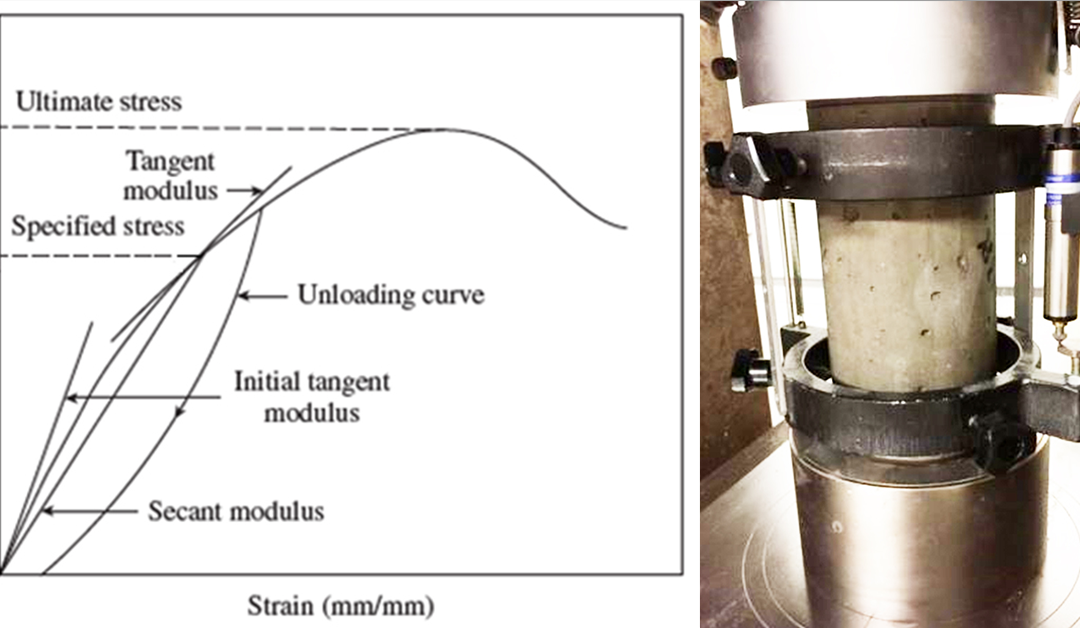


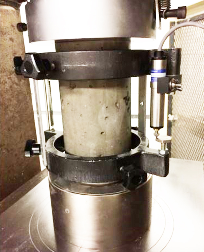 Fig. 2: Test set-up for Measuring the Modulus of Elasticity of Concrete
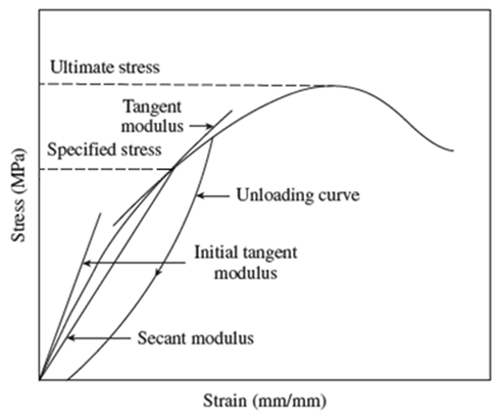


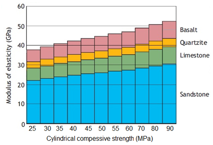

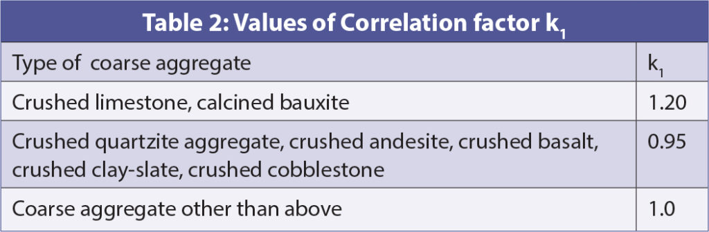
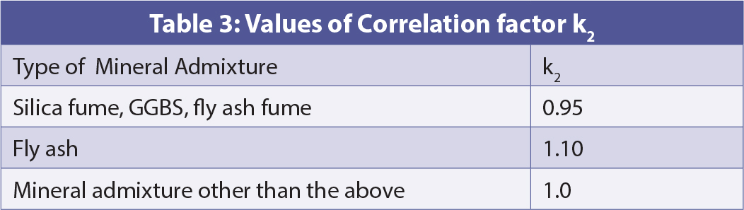


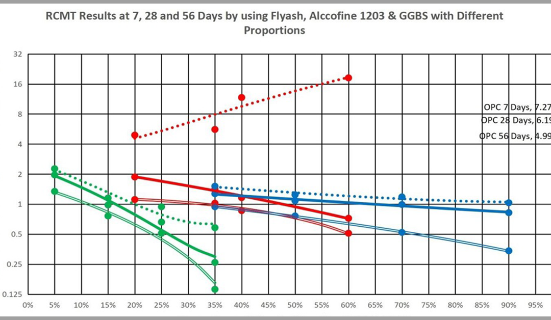


 Fig. 1: Schematic RCMT Set Up
 Fig. 2: RCMT Results at 7, 28 and 56 Days by using Different Proportions of Fly Ash, Alccofine 1203 and GGBS with Different Proportions
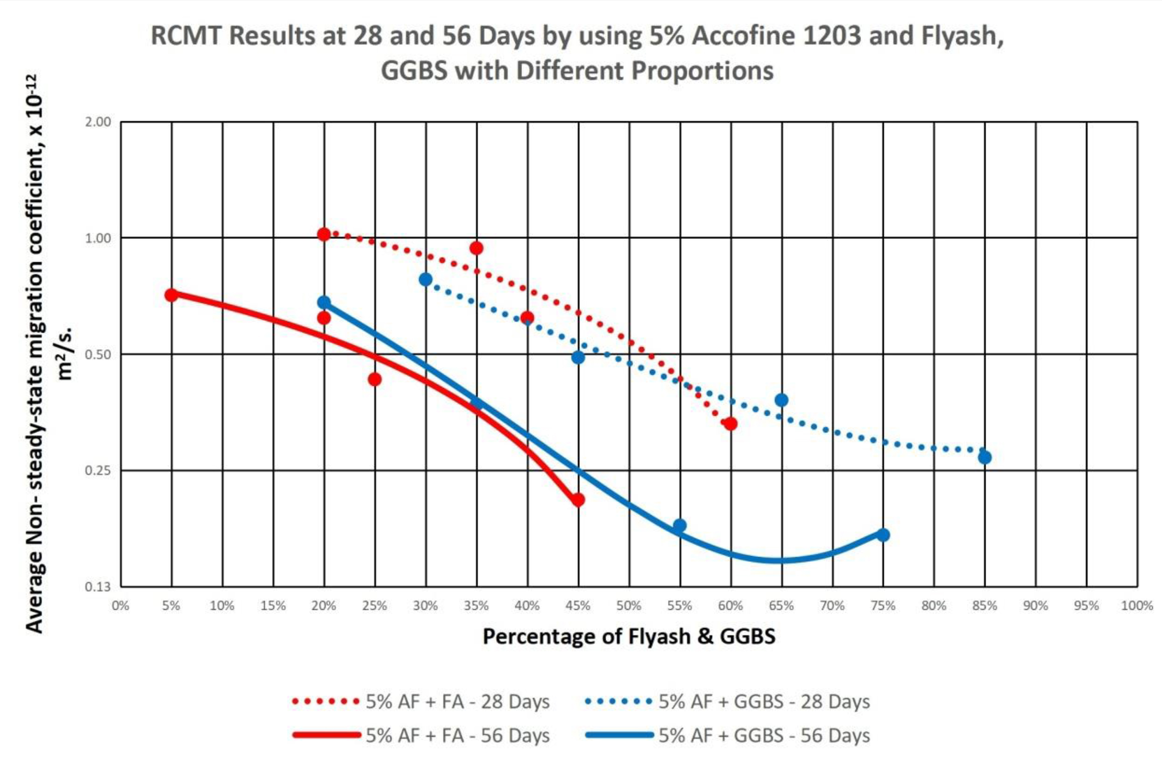 Fig. 3: 28 Days and 56 Days RCMT Results of Concrete with 3% of Alccofine 1203 and Fly Ash/GGBS in Varying Proportion
 Fig. 4: 28 Days and 56 Days RCMT Results of Concrete with 5% Alccofine 1203 and Fly Ash/ GGBS in Varying Proportions
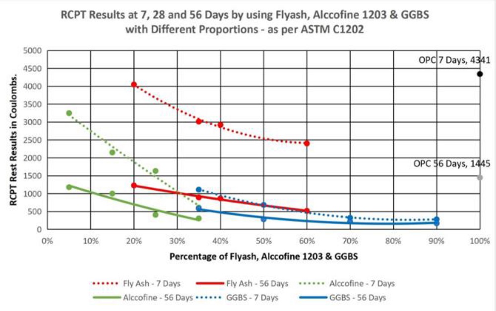 Fig.5: 7 Days and 56 Days RCPT Results of Concrete with Varying Proportions of Fly Ash, GGBS and Alccofine 1203
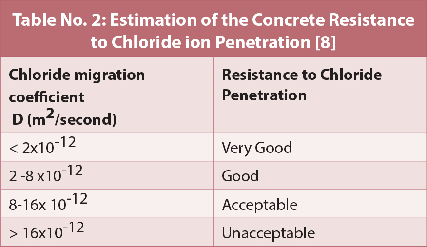
 Fig. 1: Opportunities to Achieve CO2 Reductions for Clinker (Courtesy Cembureau Website)
 Fig. 2: Opportunities to Achieve CO2 Reductions for Cement (Courtesy Cembureau Website)
 Fig. 3: Opportunities to Achieve CO2 Reductions for Concrete (Courtesy Cembureau Website)
 Fig. 4: Carbon Neutrality Roadmap 2050 (Courtesy Cembureau Website)

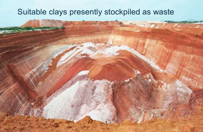 Fig. 7: Clay Suitable for LC3
 Fig. 8: CarbonBuilt’s Reversa™ Technology