Prabhat Khare Director
KK Consultants
IIT Roorkee, Gold Medalist
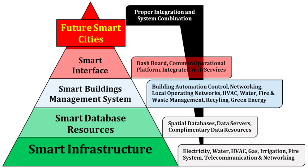
One of the biggest reasons, for rise of Smart Buildings with time has been the changing needs of building owners, who have always been looking for possibilities and potentials to increase the building’s value and marketability. Parallelly, the building occupiers have also been looking for added advantages of new technologies applied to their work place for their safety, comfort and improvement in life styles. As technological capabilities for building management continued to grow, building owners started transforming their buildings so that their occupants can experience a more customized work space. Thus, what initially started with simple standalone office technologies like access control system, work stations, photocopiers, fax machines, desktop computers and their basic integration, became more complex with emergence and integration of data and voice over IP Phones, rise of networked PCs and later internet, making highly complex integrations of facilities, operations and their controls.
At the same time many offices were also expanding from single location to multi location operations and needed technologies to monitor and control their operations using these emerging technologies. With advancement, over the time various office services and equipment and their controls were so seamlessly integrated that now in a smart building, system could tell you what time and with whom you have an appointment; on which floor of building the conference room is vacant and ready for your set meeting, it would adjust your zone temperature based on your personal data, collected from your body
mounted devices, and will guide you to the elevator or space to use. With such level of automation, a building proposition becomes very attractive to prospective tenants or businesses looking to rent out the business spaces. Since for businesses, employees’ costs are a number one operational expense, losing one employee is the equivalent of losing 1.5x their cost because of the lag times associated with hiring and training. Because of this, many businesses emphasize employee retention, engagement, and satisfaction as most critical factor of doing business. A smart building that offers customized and personalized decision making at the fingertips of its occupants, is a building that is more likely to attract and retain its tenants or businesses.
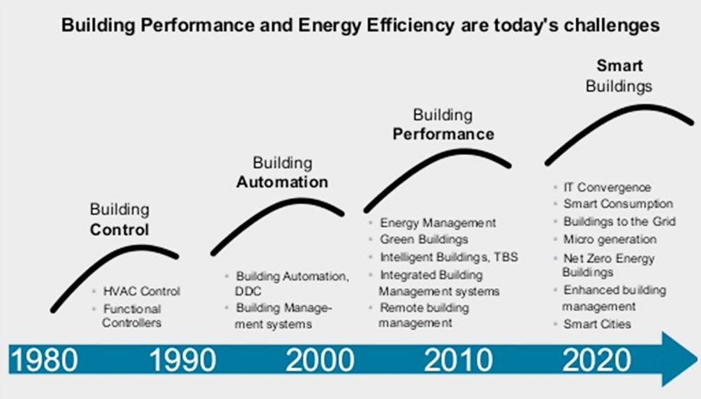
DevelopmentOf Building Automation Over TheYears From Beginning Till 1980
From the 17th century onwards, systems were designed for temperature control, the mechanical control of mills, and the regulation of steam engines. During the 19th century it became increasingly clear that feedback systems were prone to instability. A stability criterion was derived independently towards the end of the century by Routh in England and Hurwitz in Switzerland. The 19th century, too, saw the development of servomechanisms, first for ship steering and later for stabilization and autopilots.
However, its credit goes to Warren Seymour Johnson (November 6, 1847 – December 5, 1911), an American college professor who was frustrated by his inability to regulate individual classroom temperatures. His multi-zone pneumatic control system solved the problem. Johnson’s system for temperature regulation was adopted worldwide for office buildings, schools, hospitals, and hotels – essentially any large building with multiple rooms that required temperature regulation.
In the next decade or so, the non-residential control industry evolved rapidly to create a fully automatic control system operating steam/hot water, and eventually ventilation and air conditioning. With most controls and interestingly, the control logic (algorithms) operated by compressed air (air logic!).
Up until the 1970’s almost all controls (thermostats and valves) and even central control stations for large commercial buildings continued to be pneumatic. Not surprisingly, in 1980’s the conversion from pneumatic control to electric controls began with digital computers taking over the control, while most equipment in the space remained pneumatic.
1980 – 2000
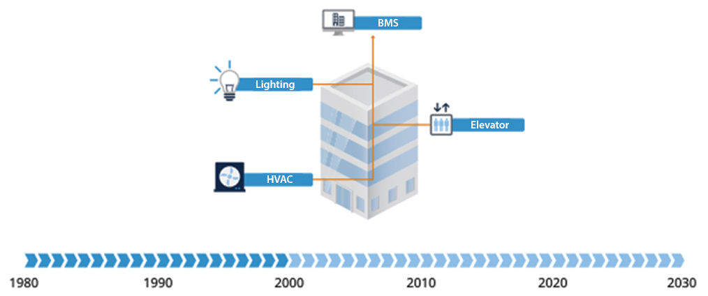
By the late 1980’s the central computer began to give way to distributed digital computers (essentially process controllers) located on individual devices and communicating back to the central system. Not surprisingly, the data produced from such systems often contained valuable and sensitive information about building operations including off-normal conditions, occupants comfort problems, resource consumption details and lead to development of processes to improve them and become more efficient. During this period, the building had a standalone central building management system (BMS) with one or two sub-systems, isolated from each other, typically used to control heating and air conditioning, the lift or lighting systems and separately handling water and wastes. The control implemented by the BMS included simply switching on or off the right equipment at the right time of the day or year.
2000 – 2020
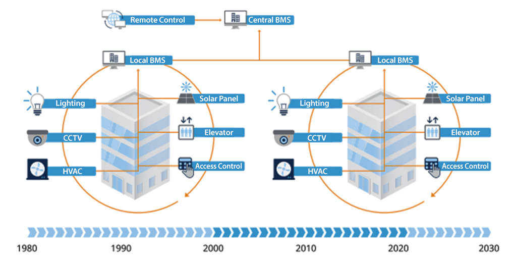
This situation rapidly changed as in response to high energy cost which forced building owners to see consumption of electricity as well as other resources like water, gas, air etc., not as a freely available commodity but as a cost of doing business. This forced them to look the conserving these resources and thus began a need to monitor and control them. This initiated the process of monitoring building performance (first locally and then remotely), and then began entry of a wide range of new systems in the building eco-system including access control system, smart metering, solar panels, climate control, automatic fire detection system, PA System and AV systems, improved HVAC and Water management systems. With time as semiconductors started becoming more powerful and their cost started to fall, low cost microchips started making inward ways in controls and automation and with explosion of Internet in 2000 as well as cloud computing, enabled a staggering range of new applications and services, as well as their complex integration. BMS was now called iBMS, with the‘i’, standing for integration or intelligent, and the buildings were called intelligent because of their highly complex networking.
2020 And Beyond
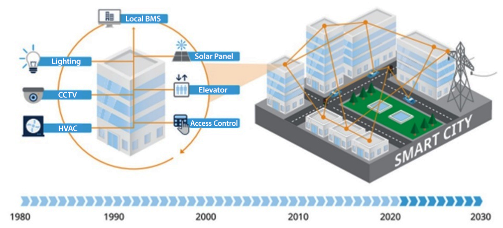
Current trend of merging of Green technologies and Intelligent building which clubs the best of both areas to form the basis of smart buildings, and is not just another incarnation of industrial control systems (ICS) or simple building management system (BMS) because smart buildings are not only just interconnection of various controls but are almost like an self-sustaining living entity connected to internet and constantly responding to changing requirements by altering their own operating parameters to meet customer needs. Also with the deep proliferation of IoT technologies, owners could tap into boundless possibilities for optimizing property operations without incurring outrageous costs – trend which is reshaping the building automation as well as building industry itself.
Progression Summary – Standalone Buildings Control To Smart Buildings Over The Decades
What Is A Smart Building?
Having gone through the development phases of building management system, the first question arises as what makes a building a Smart Building? There is no specific definition of smart building as many experts have given varied definitions based on the buildings use, however broadly a smart building can be defined as a building which is one that is both intelligent and green. It is a building that uses best of available technologies and processes to create a facility which as a principal, apart from incorporating sustainable features in its design and construction, must also have efficient resource utilization, providing a healthy environment to the occupant to improve working productivity, reduce waste which means less pollution and less environmental degradation. This building must have systems to reduce/eliminate adverse impact on environment and human’s health. A building can be considered smart if it incorporates above sustainable elements with energy efficiencies throughout their life cycles.
Expanding above basic definition, smart buildings must also have systems which provide timely, integrated information of about building occupancy, use, operations and maintenance to its owners and other stake holders so that they may make timely, relevant and intelligent decisions to perform in a better way. These systems must effectively evolve continuously with changing user requirements, ensuring continued and improved operations throughout their life cycle during which these system must continually optimize the O&M of building for betterment. These systems must meet the needs of the present without compromising the needs of future, which are measured in three interdependent dimensions: environmental/ energy initiatives, economic prosperity and social responsibility.
Thus a smart buildings has a fully networked systems of all smart sub systems, which work independently as well collectively by interacting intelligently, thus optimizing a building’s performance. A system, which collects operational and functional data on a continuous basis, and constantly changing lined parameters to create an environment that is conducive to the occupants’ goals and making the place conductive for occupier to work. Such automated fully integrated systems tend to perform better, reduce dependency on human judgment, cost less to maintain and leave a smaller environmental imprint than individual sub-systems. It is worth mentioning that since each building is unique in its mission and operational objectives and therefore, these intelligent system must balance short-and long-term needs accordingly. Smart buildings provide a dynamic environment that responds to occupants’ changing needs and lifestyles. As technology advances, and as information and communication expectations become more sophisticated, networking solutions both converge and automate divergent technologies to improve responsiveness, efficiency, and performance. To achieve this, smart buildings converge data, voice and many other complex and varied information, fetched from buildings operations to control various facilities and facilitates a constantly evolving improve user satisfaction, better space utilization, excellent energy conservation, comfort and resource conservation.
Fundamentals Of Smart Building
Broad outlines of the intelligent and green buildings that converge to form the basis of a smart building are given below:
Green Buildings And Their Indian Context
In India, the Green Building Code is a mix of many of codes and standards contained in the by-laws of the National Building Code, the Energy Conservation Building Code (ECBC) and in the norms set by the ratings programs, such as Leadership in Energy and Environmental Design-India (LEED-India), the standards and guidelines put down for the Residential Sector by the Indian Green Building Council (IGBC), TERI-GRIHA and other such certifications as well as Bureau of Energy Efficiency (BEE). Basic and general guidelines for efficient energy usage in the National Building Code (NBC) do exist but they are merely guidelines.
Intelligent Buildings And Their Indian Context
An intelligent building is broadly defined as a building that uses both technology and process to create a facility that is safe, healthy and comfortable and enables productivity and wellbeing for its occupants. An intelligent building provides timely, integrated system information for its owners so that they may make intelligent decisions regarding its operation and maintenance. An intelligent building has an implicit logic that effectively evolves with changing user requirements and technology, ensuring continued and improved intelligent operation, maintenance and optimization. It exhibits key attributes of environmental sustainability to benefit present and future generations. (CABA Steering Committee).
The idea of leveraging intelligence to enhance building performance, either for energy efficiency, resource conservation, environmental impact or occupant comfort and thereby obtaining credits is also acknowledged by USGBC. “If the objective is clear, the credit system under LEED is geared to recognize building performance that has been enhanced by automation and IT-centric intelligence,” states USGBC. An intelligent building can also be defined as “the building that combines the best available concepts, designs, materials, systems and technologies in order to provide an interactive, adaptive, responsive, integrated and dynamic intelligent environment for achieving the occupants’ objectives over the full life span of the building.”
An Intelligent Building provides a productive, cost effective environment through the optimization of structure, systems, services and management as well as the interrelationship between them. It integrates various systems (such as lighting, heating, air conditioning, voice and data communication and various other functions) to effectively manage resources in a coordinated way to maximize occupant performance at least operating cost and investment with savings and flexibility. They yield cost reductions in all these areas by optimizing operations by using intelligent and automated controls, smart communication between sub systems and managing them efficiently and effectively all through their life cycle. They also guard against R&M costs, employee engagement time, productivity loss, revenue involved and customers expectation and level of satisfaction. The intelligent systems installed in these buildings make them perform better, cost less to maintain by leaving a smaller carbon foot prints compared to conventional buildings and simultaneity providing a much improved conducive work environment to occupant.
Convergence Of Green Building And Intelligent Building – Smart Buildings
We spend up to 90 percent of our lives in buildings, and we believe that everything people do in life deserves a perfect place to do it. In a world where our fundamental health, safety and wellbeing expectations have been deeply impacted with the anxiety of a new virus, buildings should offer a haven. Ideally, a perfect place to learn. A perfect place to grow. A perfect place to prosper. While it’s true that today’s buildings should be efficient, reliable and safe, yet adaptability is crucial. Smart building interact with the people, systems and external elements around them and where various control systems are utilized to capture information and communicate directly to the each other as well as with building’s IoT devices and facility management software, to make buildings perform better and eliminating need of human intervention and judgment. In smart building, actual performance of building is measured accurately and in real time for continual performance improvement. The building information system learns from past experiences and real-time inputs and adapts to the needs of the people and the businesses within them by improving comfort, efficiency, resiliency and safety. Today there is a new need: to protect people from COVID-19.
When we use technology to support the people in buildings, we create environments that care.
Thus we can safely summarize that a smart building must have following quantifiable and measurable parameters:
Data Capturing, Storage, Retrieval And Analysis
The building must have system to handle vast range and data related to building operations and occupancy including their variation over the 24 hours operations.
Minimal Human Control
The building controls must be designed so that it manages itself with least human intervention, to a very high degree of independence irrespective of level of complexity both in operations as well as controls since it is practically becoming impossible for a human operator to manage the building’s various systems manually.
Optimization
The building system must optimize the various operations like lightings, HVAC, Water and Waste management, Lift and Escalator operations and must generate timely alarms for any sort of abnormalities so that humans can take necessary corrective actions before any major damage happens.
Performance Quality
The building system must improve upon building performances on all fronts, be it Energy management, managing footfalls, space utilization, resource allocation, working efficiency, maintenance, waste management, recycling, environmental impact and employee well-being etc.
Also we can see here that for a building to be smart, it must be green building and should have various intelligent control system installed at strategic locations to monitor its operational performance on real time basis and provide timely feedback to concerned team for making intelligent decisions in order to manage resources.
However challenges as applicable to new construction and old buildings differ are summarized below:
There are two more common challenges as summarized below:
Occupant Productivity And Comfort
Occupant productivity has a significant measurable impact on the ROI calculation. Given that energy costs represent about 1% of the overall cost of doing business and investment expenses are about 10%, staffing costs can represent up to 85% of the total cost of doing business. Any improvement in productivity can therefore have a significant positive financial return.
Life Cycle Benefits
Depending on how the life cycle cost analysis (LCCA) is addressed, this could potentially enable facilities and organizations to attain their long-term sustainability goals by developing their environmental monitoring systems to generate pertinent data. Therefore, keeping in mind that intelligent technologies are installed to deliver effective payback and long-term returns, it is critical for such systems to incorporate LCCA.
Building owners typically perceive that smart buildings will cost more. In reality however, and the fact is just opposite as considering the complete life cycle of a building the smart buildings ultimately cost less – the capital expenditure or first cost of doing a more integrated concept typically costs the owner more, however the lesser operating costs and enhanced productivity compensates the same over the complete life cycle cost of building resulting in a significant saving. Typically, operations-related impacts account for over 80% of life cycle impacts in buildings. Owners’operating costs are significantly lowered as a result of more efficient operations and better control, enhancing a building’s asset value. By enhancing connectivity between building systems and users, smart buildings help to balance the operational objectives and economic performance of buildings with emphasis on scalability and changing priorities. In an endeavor to provide a comfortable and reliable environment, smart buildings essentially help achieve a reduction in energy consumption, use resources more efficiently, and explore renewable alternatives that enable them to be financially, as well as environmentally sustainable assets over time. Reducing operating costs enhances a building’s asset value.
Smart Technologies For Smart Buildings
The range of Smart technologies and their controls which make a building intelligent are extremely wide and limited only to the imagination and budgets of the architects/engineers designing the building however, below given is the list of some of the basic smart technologies/sensors which are majorly used to make building intelligent and in turn when clubbed with green technologies make them smarter.
The list can never be comprehensive as the technology is progressing at much faster rate now than a decade back.
The current building automation technologies can address the following three major needs of building owners and tenant:
Facilitate people using the building to become active agents in the utilization, creation, and evolution of spaces that support their activities;
Preserve and improve the investment and ROI for the building owners and managers; and
Reduce the impact on the environment by the building, from its initial construction stage through its life Labor costs can be reduced by 40-60% over the life of the building as it requires less labor during the initial installation and requires less labor to maintain the building. The ability to save money also extends to energy savings, as it can reduce the energy costs in a building by making it more energy efficient whereby recouping 20-60% energy savings that would otherwise have been lost by traditional electrical infrastructure.
Network Convergence
Fully networked systems collects operational information of building to optimize the building’s performance and constantly create an environment that is most conducive to the occupant’s goals. This convergence reflects an evolution of the building systems to an IP network to internet connectivity. Optimizing energy usage and costs is the financial advantages for building owners to integrate their systems. The information is further addressed in some of the cases where the goal is to manage a portfolio enterprise and lower the cost of ownership by attacking energy, cost of deferred maintenance, operating cost, space utilization, and asset management. Once the utility bill is integrated with the building controls system, supportive diagnostic information can be presented and made easily accessible to staff. This allows them to instantaneously look at the information and adjust any issues themselves instead of waiting until end of the month thus saving time, energy, efforts and money by attacking the root cause of problem as and when it arises.
Conventional buildings suffer from the inability to communicate lease aside intelligently, the large amount of data that is generated in its operation during the building’s life cycle. A converged network solution allows a higher level of connectivity for a variety of products from multiple manufacturers. This results in benefits such as cost effectiveness, process improvements in facility automation, monitoring and management, and more efficient real estate portfolio management. Streaming building control and utility data into a shared network enables optimum management of facilities by connecting various silo systems and applications.
Integrated Building Control Systems
Programmed, computerized networks with internet connectivity of electronic devices are employed for control and monitoring of systems such as HVAC, lighting, security, fire and life safety, and elevators. Known as building automation systems (BAS) and building energy management system (BEMS), these solutions typically aim at optimizing the operational performance, start-up, and maintenance of building systems and greatly increase the interaction of mechanical subsystems in the building.
This leads to improved occupant comfort due to optimization HVAC, Illumination, energy consumption, and cost-effective building operation like Security of building occupants and assets, In-building use needs: room reservations (office buildings), way finding (hospitals, hotels), asset visibility (hospitals) with Human-centric design: allowing humans control over their own micro climates. All these can be controlled and monitored remotely or from a centralized system with a minimum human-in-loop factor.
Building automation systems (BAS) and building energy management system (BEMS) vary in capability and functionality, but are all designed to provide centralized oversight and remote control over lighting, HVAC, security, fire and life safety, elevators, water management, and AV technologies.
Structured Cabling Infrastructure
Based on the Telecommunications and Electronic Industry Association 568 Standard, a structured cabling solution (SCS) can significantly increase the lifespan of cabling infrastructure in a building, obviating extensive changes or expensive upgrades. A SCS integrates voice, data, video and other buildings cabling systems. A SCS is an open system architecture that is standard based and can reduce construction costs for the cabling infrastructure by as much as 30% and 25%-60% for cabling related changes. Other direct/ monetary benefits that can be realized are minimized upfront costs due to labor and material savings, increased lifespan and durability, and minimal maintenance costs. The ability to run data signals and power to the devices over the same cabling infrastructure can be a dramatic cost saver in high labor rate construction projects. Several additional advantages are the relative ease of expandability and adaptability for rapid and easy changes involving minimal disruption, the logical outcome is faster ROI, better utilization of installed cabling, and a lower total cost of ownership.
End-users are demanding suitably designed cabling infrastructure, balanced with desired power and cooling thresholds which are reliable, interoperable, and scalable over time. These challenges arise as buildings integrate more sophisticated voice, data, and video equipment into applications. By consolidating/integrating cabling from multiple stand-alone systems, material and labor inputs can be reduced, thus providing savings in initial construction costs.
Communication Infrastructure
Smart buildings are typified by their innovative qualities, facilitated by the integrated design process. Building owners, developers, and managers are increasingly committed to providing better services to the tenants and occupants by way of increased voice, video, and data integration and communication, and these expanding capabilities not only offer better management of buildings and associated operational costs, but also enhance the well-being of the occupants. A converged voice, video, and data network streamlines the asset allocation, tracking, and management process, which improves security and optimizes flexibility, and improves interaction and integration between the various individual IP-based systems. Communication services help anticipate increasing demand for complex and integrated networks. Communication allows all types of users to not only improve efficiency and reduce operating expenditures, but also create opportunities for unique interaction between buildings and their users. Given the increasingly competitive business environment for real estate, the presence of valueadding network and communications technology may serve as a compelling differentiator in a market increasingly saturated with look-alike properties.
Water Conservation Technologies
Water is a scarce resource and its scarcity has always been an ever- present challenge, and thus this area in building operations offers tremendous potential scope for water conservation technologies and products. One such option that has been displaying growing potential is the application of integrated monitoring and control of water use. By networkingvarioussensors andflowmetersfromwaterincomingsupply, its consumption/utilization points and then at final discharge point in conjunction with treatment and recycling of water, facilities managers can monitor the entire water utilization cycle in building.
Total realistic life cycle cost of the water system management is, for the first time, within the grasp of owners and developers however this new level of integration will help companies establish a single source of information of water utilization while increasing both the overall sustainability and conservation of a precarious natural resource.
Fiber To The Telecom Enclosure (FTTE) Or Zone Cabling
With commercial industry relying heavily on solutions provided by information technology, the network infrastructure is more critical than ever. The cost to business for installation and maintenance is a large investment. Users seeking data communications architectures that support a wide range of network applications can use a Telecommunication Industry Association (TIA) standards based solution: Fiber-to-the-Telecom-Enclosure (FTTE) or Zone cabling. The FTTE architecture extends the fiber optic backbone to telecom enclosure closer to workstations throughout a building. The telecom enclosure can then distribute a flexible topology of mixed media and power to the devices using copper category cable, fiber optics, coaxial cable, and A/V cable. As a result, buildings can benefit from more useable real estate due to the removal or consolidation of the telecommunications room on each floor. Also, there is a 20-30% cost reduction on cabling due to consolidation and removal of proprietary networks, improved network performance, single contractor/integrator vs. several specialists for disparate systems, and a substantial reduction in cost and disruption to staff when making changes within work areas.
Electrical Architecture
To meet the needs of flexible and integrated infrastructures, electrical infrastructures has to be smart, flexible, adaptable, and are able to serve as the integrated center for lighting, energy, HVAC and control systems. The new programmable environment combines a new electrical infrastructure that replaces the traditional pipe and wire electrical systems with embedded lighting controls that are connected together through nodes on a network.
Integrated AV Systems: (SSH) Over the past several decades, audiovisual (AV) technology has evolved from simple, piecemeal loudspeakers and projectors used as presentation tools into integrated and networkable systems capable of linking organizations and their facilities in new and dynamic ways. The convergence of AV and IT technologies has raised the bar for usability and systems integration, especially in intelligent and green buildings where user comfort, energy efficiency, and asset management are key features.
A modern intelligent conference room may include a networked projector and/or LCD displays, intelligent lighting and window shade systems, a digital audio system, and a high-definition videoconferencing system. This in few cases may be like a virtual meeting room with3D projections of images. Based on requested capabilities in the meeting invite, the AV control system would take over the task of turning on the AV components, setting them to the proper operational mode, and adjusting the room temperature to a comfortable level prior to the meeting start time. Ambient light sensors installed in the room would measure the amount of incoming natural light (which is becoming more prevalent in green building), adjust window shades as appropriate for the function, and supplement the natural light with the interior lighting system to achieve the proper environment for a presentation or videoconference. The videoconference bridge can be made to dial at preset time of meeting so all attendees have to do is enter the room.
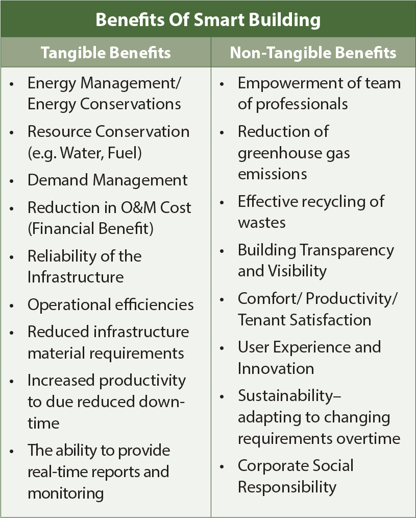
Benefits Of Intelligent Buildings
Smart buildings have been getting increasing attention all across the Globe due to their potential to reduce building energy costs, mitigate greenhouse gas emissions, reduce water consumption, and add value to the buildings given the savings and the positive effects on occupant safety, comfort and satisfaction. Actions taken to reduce building energy consumption and minimize fossil fuel pollution will have lasting environmental effects given that most power-plant- generated energy is produces by fossil fuels. Processes, building and system design and high-performance technologies are being sought to reduce energy consumption and mitigate the production of greenhouse gas emissions. This can be summarized as below:
Drivers For Smart Building
Green Building Movement
Motivated by a desire to appear environmentally conscious, many commercial facilities have adopted “Green technologies” in order to earn “Green and Sustainable” certifications. The Green Buildings Ratings and Certification process has gained tremendous momentum over the last few years. Below is a data given (Ref CII Data), many of these building may just be Green Buildings yet that is a step nearer of making them a Smart Building.
Post COVID-19, growth in green building market in India is expected to bring about enormous economic growth by creation of a new industrial sector. The notion of green building still being new in India, there are very few number of existing professionals in the sector. But as the market grows, there will be demand for architects, technicians, energy experts, environmentalists, consultants etc. having adequate knowledge of the sector. Some of the green building rating agency providers like IGBC or GRIHA have already started building professionals dedicated for green buildings. In next one decade or even less, the trend will enhance remarkably. As the worth of green buildings is being perceived by more sections of the society with the passage of time, the ultimate objective of sustainability i.e. economic development maintaining the environment looks easy to achieve.
Energy Performance Improvement Movement
Bureau of Energy Efficiency (BEE) has took up various policy and regulatory initiatives to enhance energy efficiency of building sector namely ECBC (Energy Conservation Building Code, a code developed for new commercial buildings on 27 Ma7 2007 and sets minimum energy standards for commercial buildings having a connected load of 100kW or contract demand of 120 KVA and above). BEE had proposed ambitious targets for the 12th plan period i.e. 75% of all new starts of commercial buildings are to be ECBC compliant by the end of the 12th plan period and 20% of the existing commercial buildings reduce their energy consumption through retrofits.
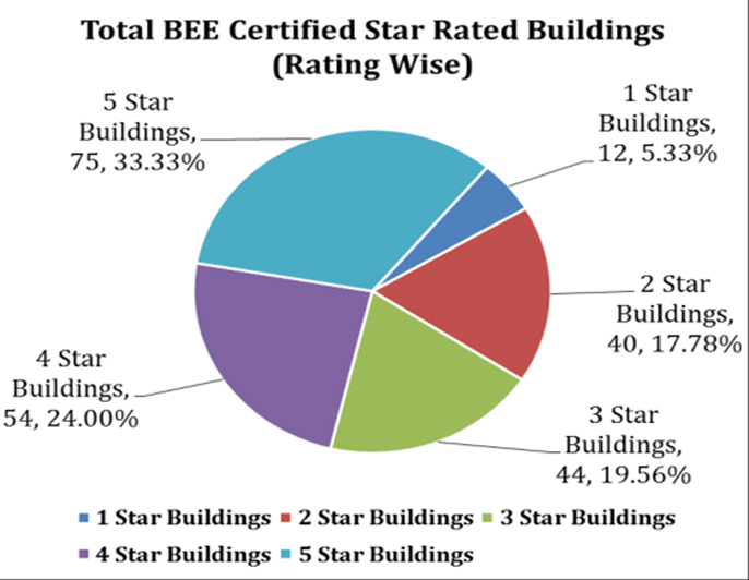
To create a market pull for energy efficient buildings, BEE developed a voluntary Star Rating Programme for commercial buildings which is based on the actual performance of a building, in terms of energy usage in the building over its area expressed in kWh/sq. m/year. This Programme rates buildings on a 1-5 star scale, with 5-Star labeled buildings being the most energy efficient. So far, about 225 buildings have been rated under various categories.
This has been further categorized in following four sub-categories based on their usage:
Star Rating Scheme for Office Buildings (166 )
Star Rating Scheme for BPOs (45 )
Star Rating Scheme for Hospitals (12 )
Star Rating Scheme for Malls (2 )
The distribution of above BEE certified buildings is given below in following categories:
Buildings As Per Star Ratings
Buildings As Per Their Use/Application
Buildings As Per EPI Range
Distribution Of Total 225 commercial buildings have been star rated under different categories of buildings as on date. (Ref BEE Website)
EPI is the energy used per unit area measured as kWh/m2/year or kWh/person/year. Energy conscious buildings in India have achieved EPIs of 100-150kWh/m2/year. The national benchmark is 180kWh/m2/year. Buildings with EPI of 180kWh/ m2/year are ECBC compliant.
Complementing the efforts of the Government of India, the ECBC has been integrated in other rating and compliance systems being followed in the country such as EIA (Environmental Impact Assessment) for large area development under MoEF (Ministry of Environment and Forest), Green Rating for Integrated Habitat Assessment (GRIHA) rating system of ADARSH and Leadership in Energy and Environmental Design (LEED) rating system of the Indian Green Building Council (IGBC).
The key drivers fueling this trend are energy efficiency prerogatives and enhancement of buildings’ operational performance on the part of building owners and managers. Other factors contributing to this trend include a desire to substitute environmentally friendly alternatives, renewable resources, and integration and intelligence benefits through incorporating intelligent building solutions. While there are a few challenges concerning high capital costs, low awareness, and receding economic conditions with a sluggish construction market, green certifications are projected to grow steadily over the next five to seven year period.
By enhancing connectivity between building systems and users, intelligent products and technologies help to balance operational objectives and the economic performance of buildings with due emphasis on scalability and changing priorities. These products and technologies, and the buildings they retrofit and sustain over time, stand to benefit from green measurement tools in reaching out to the larger marketplace for confirmed acceptance and propagation. Results achieved through the deployment of intelligent products and technologies in buildings make such intelligent solutions imperative to the success of a building’s environmental profile and increased adoption.
Intelligent buildings transcend integration to achieve interaction, in which the previously independent systems work collectively to optimize the building’s performance and constantly create an environment that is most conducive to the occupants’ goals. Additionally, fully interoperable systems in intelligent buildings tend to perform better, cost less to maintain and leave a smaller environmental imprint than individual utilities and communication systems.
Each building is unique in its mission and operational objectives and therefore, must balance short and long-term needs accordingly. Intelligent buildings serve as a dynamic environment that responds to occupants’ changing needs and lifestyles. As technology advances and as information and communication expectations become more sophisticated, networking solutions both converge and automate the technologies to improve responsiveness, efficiency and performance. To achieve this, intelligent buildings converge data, voice, and video with security, HVAC, lighting and other electronic controls on a single IP network platform that facilitates user management, space utilization, energy conservation, comfort and systems improvement.
Smart Buildings – Risks, Future And Rise Of Smart Cities
Risks: The smart buildings not only deliver advantages, but also have their associated risks which anyways comes with all new technologies, most critical of them is cyber-attacks. Since thousands of devices are connected to the Internet, there are many new“attack vectors,” as they are termed. These devices can be exploited by attackers to penetrate the building’s IT system, after which it’s simple to manipulate data and block functions of the building. Also with these smart technologies, the skill sets of operators would need an up gradation which would demand convergence of conventional engineering knowledge of process/ machine with that of various other new technologies.
Future: As the society progresses, the market for smart buildings is expected to grow at a rapid pace. According to the market research firm Gartner,
5.8 billion connected devices will soon be in use worldwide, an increase of 21 percent over 2019 (4.8 billion devices).
Experts expect the largest growth to be in the field of building automation. 230 million devices were connected worldwide in buildings in 2018 and that figure will be 483 million in 2022. Their common objective: To make working and living more convenient and counteract climate change by efficiently utilizing the resources.
Rise Of Smart Cities
With rise of Smart Buildings, the day is not far off when initially the community living and progressively cities will move toward same approach and it is expected that there will be a steady increase of smart city development around the world over the next seven to ten years, with a total value of the global smart city market projected to exceed $2.5 trillion by 2025. As our physical and digital worlds become intertwined, we have the opportunities to witness a future of continuous and lasting change, and digitalization is enabling smart cities become reality.
Conclusion
A building can be made smart by using intelligent technologies which will provide a tangible and significant return on investment. Post COVID-19, the construction industry is expected to bounce back and also expected to experience rapid growth, a growth which must be sustainable considering the referred pandemic, society has witnessed and only option is to go for smart building; however, the deployment and success of the solution will ultimately rest on the capability and experience of the project team as well as way the integration is done. The return on any of these additional investment will repay itself in much lesser time than planned since with time the as the prices of semiconductors keep following the Moore’s law, resulting in the lower cost chips. The lower cost of chips means, lower cost of various control system and technologies being put in as well as the lower cost of implementation of these intelligent system/technologies than traditional technologies. Also life-time operating costs will significantly lower and with more automation, labor costs are also likely to drop significantly, and more and more buildings will opt for converting to intelligent buildings. The time will come in near future when these smart building will certainly pave way for smart cities, a concept whose seed were sowed few years back by Honorable Indian Prime Minister of India.
B. Bhattacharjee
Emeritus Professor
Civil Engineering Department, IIT Delhi
Introduction
Modern concrete composite is a versatile technological material. The versatility manifests itself in the form of: a) mould-ability ranging from driest roller compacted concrete (RCC) to self-compacting concrete (SCC); b) strength ranging from 5-10 MPa compressive strength for mass concrete to 200 MPa (and higher) grade for Reactive Powder Concrete (RPC). RPC with fibre reinforcement ensures pseudo ductility. Thus concrete can provide robustness of dam using mass concrete and slenderness of section with high strength that is desirable in tall buildings and long span bridges. It is durable with low life cycle cost having maintenance free long service life of sections, excellent fire resistance compared to other structural and construction materials. It is imperative in many respect vis-àvis other construction materials and thereby is the most popular construction material.
Concrete is a composite having a skeleton that is particulate aggregate phase. This phase acts as inclusions in a continuous cementing matrix phase that is also responsible for bonding the particulate system together to form a hard composite material once matured. To induce pseudo ductility and for enhancement of flexural tensile strength through resistance to crack propagation, high modulus fibre is incorporated in the overall composite matrix. The particulate materials in the skeleton matrix are inert, generally obtained from natural rocks or stone. The common cementing matrix is formed by hydration reaction of a class of inorganic materials known as cement with water. Organic binders in the form of resins or monomer in liquid form can also be used, which on polymerisation through use of appropriate chemical agent can harden to solid continuous binder phase. Being costly, such exclusive organic binders are restricted to special usages e.g., repair etc. Solid binder and liquid water, when mixed in appropriate proportions can produce desirable plastic mixture. The rheological characteristics of mentioned plastic mixture can be engineered appropriately with suitable chemical and some mineral additives or even with low modulus fibre addition. Engineered concrete composite therefore is made by mixing several component ingredients. Binders can be a single component or may be again from combinations; hence as of now, possibility of many binders exists. Similarly composite material may be formed using different materials in the skeleton matrix and lastly varieties of fibres can be used to enhance specific properties as desired. Fig.1 depicts a general 3-D representation of concrete or cement based composite i.e. a chemically combined ceramic that is the most consumed material by human being after water. The advantage of mould-ability allows it to be used in fabrication of structural element both cast in-situ, i.e., in place at site or precast the elements at a factory away from actual place in structure, to transport and place by erection. Both have their relative merits and disadvantages in terms of cost, quality, feasibility etc. This article focuses on appraisal of precast concrete vis-à-vis cast in situ concrete in the context of sustainability for use in construction, with special reference to buildings in India or other countries belonging to similar socio-economic and human conditions.
Sustainability Concepts and Affordable Housing Potential
The UN appointed Brundtland Commission in 1987 defined sustainable development as “Development that meets the needs of the present without compromising the ability of future generations to meet their own needs”. Sustainability is currently understood as ability to exist constantly. Total matter in the earth’s eco system is constant according to law of conservation of mass postulated by Lavoisier in 1789. “Nothing is created nor destroyed only transformed”. The energy received by the earth from the sole source, that is the sun, in a year is also transmitted back to cosmos and hence internal energy of the earth is also conserved. Materials are transformed from one state to another by expense of energy and there by energy remains stored in the material. Such energy e.g., chemical energy stored in fossil fuel is harvested by human being and consumed. The transformation of materials e.g., CO2 to biomass materializes through carbon cycle. The natural process of photosynthesis by plant enables capture of solar energy for conversion of CO2 to biomass. The CO2 is produced by living beings through respiration and by other anthropogenic activity such as use of fossil fuel for energy and calcination of lime stone for cement etc. Thus extra CO2 is produced by human beings by virtue of consumption of fossil fuel and cement.
Fig. 1: 3-D Representation of Modern Concrete as a Composite Material System (Material A is High Performance Concrete)
The annual consumption by humanity is accounted in term of ecological foot print (EFP). This consumption includes food, livestock product, space used for built environment etc., and forest land required to absorb CO2 generated. The unit is global hectare (gha) [1]. Similarly bio capacity of the available space i.e. land, water etc., to generate the consumables is also accounted in gha. The ratio of ecological foot print to bio capacity is the number of earth required to sustain the current population with its presentday consumption pattern. Number of earth required for average consumption and living pattern of every country as well as for the entire humanity is calculated on annual basis using the mentioned accounting system. More than unity value of number of earth is unsustainable. The CO2 generation is the major issue. The average living pattern however, is not uniform across the globe. The living pattern is also related to life expectancy, education and overall quality of life. These aspects along with income are accounted in the statistic composite called human development index (HDI). Variation of HDI against EPF is for 2007/08 shown in Fig.2. Earths bio capacity/capita of 2.1gha is shown as red vertical line. A similar figure showing number of earths against HDI are shown in Fig.3 for 2016 data. Global sustainability zone is shown in both the figures. The HDI of India is lower than the minimum required for sustainability. The bio capacity and EPI per capita of India is also lower than respective global average. Hence there is scope to improve upon HDI and bio capacity maintaining EPI in a controllable level. Increasing built-up area, particularly shelter and housing of economically weaker section (EWS) and lower income group can improve HDI, although, at the cost of increasing EFP. To be sustainable, the above mentioned housing needs to be affordable i.e., within the expenditure capacity of a household. An analysis of housing affordability, based on 2011 census expenditure distribution data by author and team [2,3] demonstrate that market for affordable EWS housing are 11% and 20.5% of India’s rural and urban populations respectively, excluding land cost. House accommodation layout plan designated by Central Building Research Institute (CSIR-CBRI) and Building Materials Promotion Council (BMPTC) as economically weaker section (EWS) housing is considered in the analysis. The population below poverty line have been excluded in the above percentages, as they would not be able to sustainably retain the house in preference to purchase of minimum nutrition required. However, there is surplus supply for higher income population and a large number of houses are vacant according to an analysis carried out by JLL [4]. Such segment is also excluded in the above percentage computations. Thus there is a possibility of exploring the above scenario to enhance sustainable development in India through efficient and eco-friendly material, building and construction practise. This is true for many other countries in Asia, Sub-Saharan Africa and Latin America.
Fig. 2: Ecological Foot Print Per Capita and HDI
Industrialized Concrete Constructions for Sustainability
EFP of built-up area is equivalent to that of crop land which is most productive among land use, and is given maximum relative weightage in EFP accounting. Carbon foot print is the other major aspect related to infrastructure and building. Comparing materials and construction from sustainability angle shall look in to both these issues. For example mud as a construction material for EWS housing would consume large crop land as buildings can at best be 2 storeyed. Although the carbon footprint could be lower than concrete. Large volume of housing would favour concrete. Masonry construction with burnt clay bricks masonry unit as structural material is also likely to have higher EFP compared to concrete as building height would be restricted; also, carbon foot print would be more than that of mud and slightly less than that of concrete. Timber would have much higher EFP as equivalent carbon footprint would be much higher because of loss of forest land. Ecological footprint in general favours concrete. The advantage of concrete material system can be realized only when it is chosen judiciously from the discrete combinations illustrated in Fig.1. The construction element adopted along with associated design and construction technique implemented shall be able to minimize the sustainability concerns. The sustainability issues to be addressed in the context of concrete constructions are [5,6]: carbon foot print, life cycle embodied energy, natural resource consumption and energy implications in building during service condition. Besides, choice of materials and quality control during production, play a major role in eco-efficiency of material used. Such quality control can only be attained through mechanized and industrialized building construction. Like the concrete composite material system, the domain of industrialized building construction system with concrete is vast. The various industrialized concrete construction are illustrated in the next paragraph.
Fig. 3: Ecological Foot Print per Capita, Number of Earths and HDI (2016)
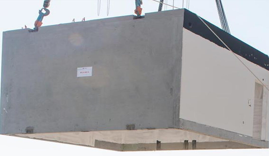
The potential industrialized concrete construction system may include Autoclaved aerated concrete panels, linear systems, insulated precast sandwich panel system, hollow core slabs and other planner systems, 3-D concrete modular system and 3-D Printed precast element [7,8]. Although not prefab, insulated form and tunnel form also are part of semi industrialized construction. Industrialized construction technologies yield thoroughly engineered concrete building products. As an example 3-D modular element is shown in Fig.4. Cement can be picked considering minimum carbon footprint and suitability with respect to exposure environment from the many options available, along with compatible admixtures. Manufactured aggregate with proper shape and packing characteristics can be selected so as to minimize paste content and hence cement content for given mould-ability, i.e. for appropriate rheological considerations. Recycled aggregate can also find a use in appropriate application. Treated waste water can be used for mix preparation as well as curing. One can also minimize water consumption by making use of curing compound. CO2 curing can help in sequestration. Overall the material system can be designed for required compressive strength. Smaller sections can be adopted for higher strength material, thereby reducing the material consumption. With lower standard deviation that can be achieved in a controlled production process, mean strength would be lower for a given characteristic strength, hence saving on costliest binder material. For enhancement of pseudo ductility and flexural strength fibres can be incorporated in the matrix by material design. Element can be designed for maintenance free service life compatible with the exposure environment and nature of loading, viz., static or fatigue loading. One can evaluate the ecological footprint of such system and minimize the same.
In a nutshell, industrialized concrete construction can provide for sustainable housing solutions as opposed to conventional prevailing non-engineered or partially engineered construction practices. Planned implementation and encouragement can provide affordable housing to large population and also ensure employment to large workforce of skilled worker with enhanced higher income. As mentioned earlier volume of required housing is enormous in absolute numbers. This implementation stated above, thereby can result in improvement in HDI towards sustainable quadrant in Fig. 2, for India. It needs mention here that, there is dearth of such educated and skilled worker at present and would need action towards creation of such work force.
Fig. 4: 3-D Modular Concrete Element
Influencing Economic Factors
At present the preference of technology is mostly governed by cost, profit and market. Cost per unit area of building is directly proportional to total area, space and specification. For similar area and specifications two factors identified in literature with respect to implementation of advanced Industrialized Building constriction (IBC) are C-factor and P-factors involving labour cost and plant and machinery costs. These factors are given by [ 8]:
These factors vary from country to country. The readily available C-factor and P-factors for some country and region are shown in Table 1. In table 1 percent cement consumption is also shown side by side. One interesting observation in the table is that higher the C-factor lower is the P-factor. Cement in precast concrete for buildings is high for lower P-factor. Further an inference is drawn from this analysis is shown in equation 3.
(P − factor) × (C − factor) ≈ 10 (3)
It can also be inferred from the table -1 that where P-factors are low, which means countries where labour cost is high, i.e., average income of skilled work force is high, cement in precast concrete for Buildings is also high that means precast concrete is favoured. Another inference that can be drawn from Fig 2 and Fig.3 in conjunction with table 1 is that countries where precast concrete is favoured rank very high in HDI, but their EFP is also high.
Conclusions
Country like India which is quite below the sustainability quadrant in HDI needs well planned strategy to enhance HDI at least to lower limit of sustainability quadrant, and, at the same time needs control of EFP. The construction and housing can play a positive role in this direction by encouraging industrialized precast concrete construction. Improvement of skill of the workforce can enhance their income and their by amplify the proportion of eco-efficient construction practices.
References
1. https://www.footprintnetwork.org/ (2019): “Working Guidebook to the National Footprint and Biocapacity Accounts”
2. Mondal Darpagiri (2017): “Optimization Of Housing Affordability”, M.Tech thesis; IIT Delhi.
3. Mondal Darpagiri and Bhattacharjee B (2020): “Housing For All: Analysis Of Possibility And Potential” Current Science. Revised Paper under review
4. JLL (2012): Affordable Housing In India – An inclusive approach to sheltering the bottom of the pyramid. 2012
5. Bhattacharjee, B. (2011) Sustainability Performance Index for Concrete. International Concrete Sustainability Conference, August 9-11, 2011, Boston, MA, USA. www.concretesustainabilityconference. org
6. Bhattacharjee, B (2010): “Sustainability Of Concrete In Indian Context” Indian Concrete Journal. Vol 84 No.07 July 2010. pp. 45-51.
7. Warszawski Abraham ( 1990): “Industrialization and Robotics in Building: A Managerial Approach”. Harpercollins College Div.
8. Elliott, Kim S. and Hamid, Z. A (Eds): (2017) “Modernisation, Mechanisation and Industrialisation of Concrete Structures”. Wiley Blackwell.
Dr. S. C. Maiti
Ex-Joint Director
National Council for Cement and Building Materials
Concrete is the integral part of the structures. Being the part and in close contact with steel reinforcements, the reinforced concrete produces structural elements and structures, which carry load as per design and provide various kinds of services, in buildings and structures.
Cement discovered and developed is the binding material in concrete. Concrete has various other ingredients: Water, aggregates, chemical and mineral admixtures, and sometimes, fibers, steel or polypropylene. Some special types of concrete e.g. Polymer concrete, high-performance concrete, high-volume flyash concrete, self-compacting concrete and very high-strength concrete are also discussed briefly.
Various stages of concrete e.g. elastic and plastic concrete- their significance, sustainable concrete construction and green concrete, the special property of concrete i.e. creep, the probable life of concrete structures, and the future with cement – less concrete are also discussed.
Introduction
Versatility of concrete is widely accepted and well known. In good olden days, when Joseph Aspdin, a Leeds bricklayer, stone mason and builder used concrete for making slabs, there were apprehensions in using concrete in all types of structures as the construction of arches with masonry was common. Aspdin patented ‘Portland Cement’ in 1824.
The process of manufacture of cement consists essentially of grinding the raw materials (limestone and clay), mixing them intimately in certain proportions and burning in a rotary kiln at a temperature of upto about 14500 C, when the material sinters and partially fuses into balls known as clinker. The clinker is cooled and ground to a fine powder, with about 5% gypsum added, and the resulting product is the commercial Portland cement1 . Cement consists of four compounds: tricalcium silicate (C3 S), dicalcium silicate (C2 S), tricalcium aluminate (C3 A) and tetracalcium aluminoferrite (C4 AF). The two silicates (C3 S) and (C2 S) are primarily responsible for the strength development in concrete.
Like all other disciplines, concrete production initially was an art, its science was developed later, when mechanics and structural engineering could be applied to understand the micro and macro properties of concrete. We apply a number of limit states to compensate the imperfections and intrinsic complexities like shrinkage, creep, fatigue etc. Prof. Neville, after elaborately discussing all the properties of concrete in detail, concluded that concrete making is an art, as much as it is also a science.
Concrete is made of cement, water, sand, stone chips or river pebbles (we call coarse aggregates) and chemical and mineral admixtures (fly ash, ground granulated blast furnace slag, rice husk ask, silica fume etc.). The chemical admixtures change the physical characteristics of concrete e.g. setting time and workability. They can also reduce the water content of concrete for a fixed workability of concrete, thereby, reduce the water-cement ratio, and hence can increase the compressive strength of concrete. They can also produce high workability pumpable concrete for constructing high-rise buildings, roads and heavily congested reinforced concrete structures. These chemicals are mostly organic materials, their basis is either naphthalene, melamine or polycarboxylic ether. Some of the chemicals can entrain air inside the concrete, thereby making the mass concrete (with large size coarse aggregates) cohesive and other concrete, more resistant to freezing and thawing in cold climate.
The steel is used to reinforce the concrete structures, and thus we produce reinforced concrete structures. The steel is strong in both compression and tension, but concrete is strong in compression and weak in tension. The steel-concrete, combination makes the structures strong. As an integral part of the structure, steel is quite strong, except that it gets corroded in presence of oxygen and moisture. Further, chloride in moist concrete can also corrode the reinforcement. Once reinforcement is corroded, its volume increases (about 7 times the initial volume) and cracks are developed in the concrete structures. The cracks increase day by day and finally, the structure loses its integrity, and collapses.
With its inherent weakness of cracking and corrosion of steel reinforcement, concrete has been a choicest material for making thin shell structures, starting from funicular shell to paraboloid, hyperboloid and natural shell, like Lotus temple in Delhi, Opera house in Sydney. There are number of such shells all over the world. Aesthetically and architecturally, shells are the most beautiful structures.
Different types of concrete are now produced suiting to the requirement of industry, and high rise buildings. Following are some of the special types of concrete.
1. Polymer concrete
2. High performance concrete
3. High-volume fly ash concrete
4. Self compacting concrete
Polymer Concrete
Polymer concrete or resin concrete is a concrete containing polymer, a binder in place of Portland cement and inert aggregate as filler. This concrete has high strength, greater resistance to chemical and corrosive agents, lower absorption, higher freeze and thaw durability.
High Performance Concrete
High performance concrete (HPC) is a concrete which is produced with some special properties like low permeability by adding micro filler like silica fume, flyash or ground granulated blast furnace slag (g.g.b.s.). The performance requirements can be high-strength, high early strength, high workability (including self-compacting concrete), low permeability and high durability for severe service environments. We call high performance concrete as a special concrete. But all concrete is supposed to provide high performance. The specially designed earthquake- resistant buildings and structures have to provide the required ductility to survive the earthquake forces. The fiber reinforced concrete, polymer concrete and epoxy concrete are all high performance concrete and have also to provide the required strength. Fly ash, a pozzolana and a mineral admixture, obtained as a by-product from thermal power stations, is being used in concrete to improve its properties. The Code of practice for plain and reinforced concrete IS4562 stipulates the use of at least 25% good quality fly ash or at least 50% g.g.b.s. as part replacement of low-alkali OPC, to prevent the durability risk associated with alkali-silica reaction in concrete structures, specially hydraulic structures. Some of the Himalayan aggregates may be reactive. Such aggregates react with the alkali of cement in concrete and alkali-silica gel is formed inside the concrete. This gel imbibes moisture and the volume increases causing expansion and cracking of concrete, over a period of many years. Two Indian dams (‘Hirakud’ and ‘Rihand’ dam) suffered this deleterious alkali-silica reaction. Although about 13,000 tons of fly ash was used in the structural concrete of the Rihand dam, yet the Power House structures cracked severely, because the OPC used had high alkali content, in the range of 1.2 to 1.8% as Na2 O equivalent3 .
Silica fume is a very fine and highly reactive mineral admixture for concrete. It is a by-product of ferro-silicon industries. It’s BET fineness is more than 15,000m2 /kg and is being imported from Norway, Australia and China, in condensed form. For developing high-strength Silica fume is a very fine and highly reactive mineral admixture for concrete. It is a by-product of ferro-silicon industries. It’s BET fineness is more than 15,000m2 /kg and is being imported from Norway, Australia and China, in condensed form. For developing high-strength.
High-Volume Flyash Concrete
The high-volume (more than 50% replacement of OPC) fly ash concrete is being used in many places, specially in concrete roads, in mass concrete constructions, and in Roller Compacted Concrete Dams. The recently completed roller compaced concrete dam (Teesta IV Low dam) in Darjeeling district, 160 MW, 30m height, was constructed with 65% flyash in concrete.
Such concrete has benefit of reducing OPC content of concrete and reducing heat-development in mass concrete construction, and hence controls the thermal cracking in massive concrete structures. Prof. P.K. Mehta5 of the University of California, Berkley used high-volume fly ash concrete (106kg OPC and 142kg fly ash/m3 of concrete) in the construction of reinforcement-free and crack-free foundation structure of a Hindu temple, in Hawai island, which had 28-day compressive strength of 15.9MPa. The maximum temperature rise in concrete was only 130 C.
Self-Compacting Concrete and Very High Strength Concrete
The self-compacting concrete is a recent development. This concrete is like a thick liquid, a cohesive mass, and is being used in heavily reinforced concrete sections, where needle vibrator can not be inserted. Because, there is no vibration or compaction required, faster construction is possible. The essential ingredients of self – compacting concrete are the polycarboxylic ether – based superplastisizers and a viscosity modifying agent (VMA). Very high –strength concrete (of the order of 100 MPa) is only possible using this kind of superplasticizers, which is able to reduce more than 30% of the mixing water. The silica fume or the micro-silica (about 10% by weight of cement ) is also required to develop such high-strength concrete. In self-compacting concrete, superplasticizers provide the fluidity and VMA is used to reduce segregation. VMAs are hydrophilic, water – soluble polymers having high molecular weight. Such polymers can form a network of large molecules extending throughout the mass. The size of the polymers are in the colloidal range. Hence these are called ‘colloidal admixtures’.
The self-compacting concrete (M50 grade) has been used in the R.C.C. foundation raft (3.7 m thick) of the tallest man-made structure of the world, the Burj Khalifa6 .
Creep of Concrete
In the hardened states, we sometimes call concrete as ‘elastic’ material and we measure its modulus of elasticity. Creep and shrinkage are other hardened concrete properties. The creep is the time dependent deformation of concrete, and we calculate the ultimate creep strain using creep coefficient values given in our Code of practice2 . However, for long span structures, it is advisable to determine the actual creep strain likely to take place. To most of the civil engineers it is a neglected property of concrete, and many engineers do not understand its importance. Failure of structures due to creep of concrete is rare. However, creep-induced sagging was noticed in the midspan of a bridge in an American territory in the Pacific Ocean7.
Elastic and Plastic Concrete
We have thus used the term ‘elastic’ for the concrete. Similarly, we can use the term ‘plastic’. There can be plastic shrinkage cracks, when fast evaporation takes place in fresh concrete. ‘Plastic shrinkage’ by definition, occurs prior to setting of concrete. The drying shrinkage is preceded by elastic shrinkage, which occurs, when the water is lost from concrete, while it is still in a ‘plastic’ state. Concrete contracts on drying, and we call it as ‘drying shrinkage’. Withdrawal of water from concrete stored in unsaturated air causes drying shrinkage. Then there is “autogenous shrinkage” due to withdrawal of water from the capillary pores, by the hydration of the hitherto unhydrated cement in concrete.
In mass concrete, the thermal cracking can be avoided by controlling the placing temperature. Generally, lower the temperature of concrete, when it passes from a ‘plastic’ state to an ‘elastic’ state, the less will be the tendency towards cracking. We have just discussed the elastic and plastic states of concrete. We also sometimes estimate the ‘plastic rotation’ of steel-concrete composite beams, experimentally in the laboratory, and relate it to the bending moment8. This ‘plastic rotation’ on the loaded structures is in the inelastic state of concrete.
We use ‘plastic concrete’ in cut-off wall or in diaphragm wall, in the dam project. The technique has been developed to make water-tight curtain wall, as the main element of foundation treatment for the embankment dams9. The diaphragm walls are generally excavated in panels, the excavated area being supported by bentonite slurry. The cut-off wall should behave in such a manner, that no crack is introduced as a result of imposed loading. A typical ‘plastic concrete’ mix includes gravel, sand, clay, cement and bentonite. They are mixed with water to produce a workable mass. The design of ‘plastic concrete’ wall involves section of a proper composition of the mix, to ensure the required permeability, deformability, workability, strength and durability.
Sustainable Construction and Green Concrete
The recent trend and technological innovation paved the way for new construction materials with the major focus on the sustainability in construction. The natural resources e.g. limestone, crushed stone and sand are reducing day by day, and we have to replace substantial proportion of cement and aggregates by industrial waste products such as flyash, bottom ash, blast furnace slag etc. The use of such waste products can partly solve the environmental pollution problem and simultaneously provide sustainable construction with less cement and aggregates. This can result in ‘green’ concrete using less of natural resources and use of waste materials. The coal ash consisting 80% fly ash and 20% bottom ash can replace substantial quantity of cement and fine aggregate in concrete. The resulting ‘green’ concrete will go a long way in providing sustainable construction and enhanced durability of concrete in structures.
Life of Concrete Structures
High – strength concrete (grades M70 and M80) is now a days being used in lower portion of high-rise buildings, and also in bridge girders and in spillways of concrete dams. But the strength of concrete in structures decreases at higher ages. Like human beings, old concrete structures and buildings become weaker, may be after about 80 to 100 years’ of age. Delhi Metro structures have been designed for 120 years. So also the Euro tunnel (connecting England and France under the sea). The Burj Khalifa (in Dubai), the tallest tower of the world (828 m high) is also expected to provide the service life for at least 120 years. The Hindu temple foundation built in Hawai Island is made of precast concrete blocks, and without any reinforcement. This concrete structure is expected to provide service for 1000 years according to Prof. P.K Mehta.
Future with Cement-less Concrete
So long the limestone is available, cement will be produced, and concrete structures will be built. But when the limestone reserve is exhausted, cement no longer available, cement-less concrete is the ray of hope for the construction industries. Such concrete is fly ash or g.g.b.s.-based geopolymer concrete, using sodium hydroxide and sodium silicate solutions as binders. Such geopolymer concrete using fly ash has been produced at a temperature of 650 C by Prof. Vijaya Rangan10 at Curtin University, Perth. The 7-day compressive strength of this concrete is 46.2N/mm2 . Rajamane an others11 produced geopolymer concrete using g.g.b.s. at ambient temperature of 30-350 , which had 28-day compressive strength of the order of 45MPa.
The geopolymer concrete can be used in R.C.C. with grades of concrete upto M45. Such concrete can be produced with the normal equipment, similar to those used for conventional cement concrete, and is probably, the future of concrete in structures.
Conclusions
Concrete, a versatile construction material is made of many ingredients with cement, a binding material. concrete is the integral part of the structures. With reinforcements, the reinforced concrete structures carry loads as designed and provide the desired service life, may be maximum upto about 100 years, unless they are exposed to severe environmental conditions or suffers some deleteratious reaction like alkali- aggregates reaction within the concrete. The chloride can corrode the reinforcements, if more quantity is inside or enters from outside and weaken the structures, reducing the life span. The chemical admixtures are a must in concrete, to develop the required property e.g. workability,cohesiveness, pumpability, self-compacting property and high strength.
The mineral admixtures e.g. flyash (at least 25%) or ground granulated blast furnace slag (at least 50%) produce green concrete and help in combating the deleterious alkali- silica reaction inside the concrete. The other mineral admixture i.e. silica fume (upto 10%) help in producing high strength and abrasion resistance in concrete roads and spillways of concrete dams. The creep, shrinkage, elastic and plastic properties of concrete are developed in different stages and are termed in different contexts. The ‘plastic concrete’ is used to make a diaphragm wall in dam project. The future of cementbased concrete is uncertain, as the limestone deposits are getting exhausted. The geopolymer concrete with two chemicals i.e. sodium hydroxide and sodium silicate solutions, producing about 45MPa strength is the ray of hope, and may be the future of concrete construction.
References:
1. Neville, A.M. properties of concrete, 4th edition, 2000, Pearson Education Pvt. Ltd. Singapore.
2. BIS. code of practice for plain and reinforced concrete IS: 456-2000, Bureau of Indian Standards, New Delhi.
3. Rihand dam Expert Committee Report, Vol. 1, June 1986, published by Irrigation Department, Uttarpradesh.
4. IRC, Guidelines for use of silica fume in rigid pavement IRC:114-2013. The Indian Roads Congress, New Delhi.
5. Mehta, P.K. and Wilbert S. Lngley. Monolith Foundation: Built to last a 1000 years. Concrete International, July 2000, pp. 27-32.
6. Baker, W.F. Burj Khalifa: A New Paradigm. The Indian Concrete Journal, Vol. 85, No.7, July 2011, pp, 8-12.
7. Neville, A.M. Concrete Technology – an essential element of structural design. Concrete International, July 1988.
8. Maiti, Subhash Chandra. Plastic rotations in continuous encased beams, Journal of Structural Division, American Society of Civil Engineers, Vol. 101, NoST6, June 1975, pp. 1269-1281.
9. Mirghasemi A. Ali and Moshashai, H. Plastic concrete specification, a case study- Karkheh Dam project, in Advances in Concrete and Construction Technology, publication-3, 2002, Interline Publishing, Bangalore, p.p. 210-217
10. Rangan, B.V. Fly ash – based geopolymer concrete, Indian Concrete Journal, October, 2008.
11. Rajamane, N.P, Nataraja, M.C. Lakshmanan, N and Dattatreya. Rapid chloride permeability test on geopolymer and Portland cement concrete. The Indian Concrete Journal, Vol. 85, No. 10, October 2011, pp. 21-26.
Bridges are important. It is hard to imagine a civilization without bridges. They are essential for growth and development of human society. Bridges cannot be seen merely as a structural object to cross an obstacle or a stream. They are linkages connecting people and communities. They reveal something about the creativity of Civil Engineers/Structural Engineers at the time of creation. They even speak about our identity. Even today there are more than 1 billion people around the world (which is nearly 1/8th of the world population) living in poor conditions and many of them in remote areas hungry for food and connectivity. For them, a connecting bridge means a whole lot of difference in their life. It may help them in education, medical care, access to market and a lot more.
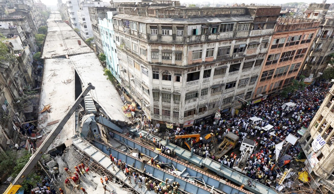
When Bridges fail, communities struggle. Development stagnates. People suffer. When a bridge failure occurs, the loss of the asset is only a small component of the total loss; it results in much greater national socio-economic consequences. The challenges that lie ahead to reduce failure risk is huge and this paper examines the circumstances and issues that contributed to a series of construction and engineering failures, to enable development of a systemic learning framework to contain and reduce design errors and potential failures and accidents.
Failures used to be rare in the past. But of late there have been a number of failures or distress in bridges and flyovers and other structures, either during construction or prematurely during service. Every major collapse is followed by intensive discussions between the authorities and Engineering fraternity. This in turn results in some changes in the codes and specifications and construction practices. However, there is no tangible improvement in safety standards in the opinion of the author and bridges continue to fail in the same manner. The story of why bridges failures are becoming more frequent is more complex than the technical details surrounding its design and construction. The problem of failures and distressed infrastructure asset is a serious one and needs to be addressed if India is to achieve its aspirations of rapid growth and improvement in the trust of lives of its people. The real cause of such failures can be attributed to deteriorating moral and ethical values, scant application of sound engineering judgment, lack of communication between designer and constructor, decision-making, economics, organization, culture, and individual and organizational hubris. To understand the real issues, one needs to examine the present situation holistically, looking into all these aspects. It is not a problem that can be resolved in a few years through the passage of a law or through a stand–alone short–term initiatives. Sustained long-term efforts are required by all stakeholders to address this complex problem of great importance affecting the society at large. This paper makes an attempt to bring awareness to the fact that welcome changes in many areas of the design-construction industry have and do come about with benefits realized as the result of catastrophic failures. The author would also like to urge that we, engineering professionals, press for change when warranted and try to extract all possible benefits from failures.
Are We Learning Lessons From Bridge Failures & Bringing Changes In Codes, Standards & Work Practices?
One of the impediments in learning lessons from failure is that the full details of many failures and outcome of the investigations are not made public. Fear of blame, lawsuits, damaged business opportunities and ruined reputations are all often cited as reasons for keeping failure cases and actual examples under the wraps, under legal non-disclosure agreements and in insurance company files. This is a global problem and not just India-centric issue, but some countries have found ways and means to at least generically share the lessons through more comprehensive failure dissemination methods and educational repositories. Structural failures are the result of human activities which, in the design and construction industry, are prescribed in part by codes, standards and industry practices. In case the investigation of a failure reveals that adherence to the practices allowed or indeed, created the cause of the failure, then it makes a good sense to critically review those codes, standards, regulations and industry practices, and if felt necessary these needs be revised. Take the example of failure of bridge over river Karamanasha in UP (NH-2). This 4-lane bridge with divided carriageway with 5 span continuous deck was constructed in the period between 2000-2003. The cantilever brackets of one of the Pier Cap failed with a bang on 28th December 2019, 16 years after construction (Fig. 1). Close inspection of the failed pier cap bracket and review of circumstances revealed that the failure occurred due to lack of adequate reinforcement in pier cap, unregulated overloading over the deck and poor maintenance of the bridge. The centre line of bearings in this bridge, carrying very high loads were placed at the edge of plate type pier with half the bearing projecting out on a cantilever bracket. Nominal reinforcement was only provided in the pier cap. The designer in defense referred to one of the clause in IRC:78 (Clause 710.8.4), which reads as under:
Fig. 1: Failure of Pier Cap Bracket of Karamanasha Bridge on NH-2, U.P [2019]
“In case bearings are placed centrally over the columns and the width of bearings/pedestal is located within half the depth of cap from any external face of the columns, the load from bearings will be considered to have been directly transferred to columns and the cap beam need not be designed for flexure.”
One of the lesson Learnt from this failure: To modify this clause of the referred code (which still exists!), which is liable to be misinterpreted resulting in collapse.
One form of “benefits”, which derives from bridge failures is the improvement of codes and practices. But there are many other benefits that manifests themselves in changes in practices of structural design, construction safety regulations, approval, oversight, inspection and other industry practices that follow catastrophic failures. There are plenty of literatures/books available highlighting “Case Studies” and “Lessons Learned” from failures. These information’s compiled based on past failures are quite useful provided the lessons are heeded and acted upon to prevent their recurrence.
Statistical Data On Bridge Failures – In India And Overseas
Collection of bridge failure/damage information, plays and important role in each era of development of bridge codes and specifications. The study of the failure of structures is an important activity related to infrastructural development. It involves different stages of planning, construction, maintenance and disposal. Although various levels of activities involved in a failure study yield limited output and outcome still, it helps in assessing associated risks with bridges during their construction or service phase. Thus, helps in assessing the performance of structures built in the past to improve the future practices. Code developers and specification writers take due cognizance of these statistical data to decide on the margins of safety and work safety specifications in code.
Recently several researchers analysed the failure of bridges particularly in the USA, China, Japan, Vietnam, etc. Literature on such statistical data is available for taking measures for mitigation of such failures [1]. Besides the failure statistics, case studies of major catastrophic bridge failures are also available in public domain for many of the failures in these countries. In one of the recent articles, Ian Firth, an acclaimed bridge expert and former President of IStructE looks back at the box-girder bridge collapses of 1970 and considers the applicability of the lessons learned to structural engineers even today [2]. The article gives clear indication that worldwide, engineering fraternity is not acting upon the past failure learnings to prevent their recurrences. This aspect is further dealt with in more details in Section 7 below.
Indian statistical data of failure is scarce. Though there are many articles written on individual failure of a particular bridge, there are very few researches done by collecting large amount of data to carry out the failure studies. The author could lay his hand to only a single article written by R K Garg, S Chandra & A Kumar of CRRI [1], which provides statistical data of failure of bridges, that occurred for 40 years, between 1977-2017. These data from 2,130 bridges (excluding culverts and foot bridges) were collected from various sources, including print and electronic media. Given below are the outcome of statistical data of failure in USA and in India, which gives many interesting information.
Statistical Data Of Bridge Failure In USA, During Service [3]
As a part of the FHWA sponsored research project in 2008, the Multidisciplinary Centre for Earthquake Engineering Research (MCEER) collected data of 1,254 bridge failures and presented in a manner which can help engineers to learn lessons. 85% of this data is taken from North America, 7% from East Asia while balance from other sources. Some of these findings are reproduced below for benefit of readers:
Fig. 2: Distribution of Failure by Function
Fig. 3: Distribution of Failure by Material Used
Fig. 4: Distribution of Failure by Structure Type
– Distribution of failed bridges by function:
91% of the failures occurred in roadway bridges while only 2% occurred in Railway Bridges. Pedestrian Bridge failure reported was only 1% while Highway failure was 6% (Fig. 2).
– Distribution of failed bridges by material used:
65% of the failures occurred in concrete bridges while 30% occurred in Steel Bridges. Other type of failure reported was only 5% (Fig. 3).
– Distribution of failed bridges by structure type:
58% of the failures occurred in Girder type bridges, 29% in through truss type of bridges and balance is on other type of bridges (Fig. 4).
Fig. 5: Age Distribution of Failed Bridges
Fig. 6: % of Failed Bridges based on Cause of Failure
– Distribution of failed bridges by age:
Age distribution of failed bridges is an important parameter for finalization of the strategy and procedure for maintenance of bridges. Fig. 5 shows the % of failed bridges in the age group of 10 years interval.
– Distribution of failed bridges by cause of failure:
On the basis of data provided between 1980 to 2012, it is observed that 47% of the bridge failure in USA is caused due to scour and floods. 15% failed due to collision with truck, ship or rail and 11% due to internal causes. The term ‘Internal causes’ here includes failure due to design error, construction error, material defect and lack of maintenance. Fig. 6 shows the % of failed bridges.
Statistical Data Of Bridge Failure In INDIA, During Service [1]
– Distribution of failed bridges by structure type:
Fig. 7 presents the details of the types of bridges during service. Bridges are constructed dominantly of RC and PSC (58% in a sample size of 622 bridges) followed by steel (including truss, plate girder, Bailey bridges and steel-RC composites) as 32%. The timber and masonry bridges are of the order of 7%, while the data for material used was not available for rest of bridges. The RC and PSC bridges may undergo highly nonlinear structural behavior causing concrete cracking, yielding of the reinforcing steel, and large deformations.
– Distribution of failed bridges component wise:
The component of the bridge, which triggered the failure, is identified and is presented in Fig. 2. The failure of the superstructures is 72%, followed by substructure (10%) and foundations (6%) of all failures. The dilapidated, as well as demolished conditions are 5% while the remaining 7% failures are of the abutment, earth retaining walls (REW), expansion joints and bearings. The failure of the foundation generally affects the pier, thus leading to progressive failure of the associated spans. However, segregation of the failure initiating component in terms of foundation or the pier might, in some failure cases, be subjective. Still, this piece of information towards identifying the affected specific component is crucial for failure analysis.
Fig. 7: Material Wise Distribution of Bridges Failed during Service
Fig. 8: Component Wise Number of Bridges Failed in Service
– Distribution of failed bridges in service based on cause of failure:
During service, the causes of failure of bridges are shown in Table 1. Various causes of failure of bridges are overloads, deterioration of material including ageing, natural disasters, design as well as construction aspects and human-made disasters, and the values are provided in Table 1. The dominant cause is the natural disasters of the order of 80.30%. Another dominating cause of failures is the deterioration of the material (10.10%) followed by the design and construction (4.13%). The overloading is the cause of 3.3%, and Human-Made disasters are 2.2% of all the failures of bridges in India.
It can be seen from the above that the failure of bridges against floods alone is a serious cause of failure of bridges in India, which is 51.2%. It is sometimes associated with uncontrolled sand mining. Sand mining has been a common practice in India to collect sand from the river bed for the use in civil engineering construction. Easy access available close to the bridge has made this practice more common to dig in the vicinity of the piers of the bridges. Excessive sand mining creates scouring around the piers, thus weakens the foundation and reduce resistance to lateral loads.
In the USA, the scouring has been reported to be more pronounced (19%, Fig. 6) than in India (0.8%). The failure of bridges due to seismic activities in India is of the order of 26.8% of all failures. Compared to this, the reported failure cases due to earthquake in USA is only 2% (Fig. 6). The reducing lower failure rates showcase the advancements made in earthquake safety research and practice in USA.
In India, storm-based bridge failures are 0.60% as compared to 0.40–8% in the USA. The scale of storm, which includes the impact from cyclone, hurricane, tornado or thunderstorm, has been more severe in the USA. Landslide induced collapse of bridges in India are not many (only 0.8%). The failures of bridges due to ice (snow) in India are also scanty.
The percentage of damage to bridges due to overloading has been observed as 3.3% in India. Compared to this, the failure rate in USA due to overloading is 13%, which is very high. The increasing trend of failures of the overloaded bridges is alarming in the USA. Though in India, the case of failure due to overloading is low, this does not give the true picture since overloading is rampant in India too. There is uncontrolled overloading by regular trucks, which is a serious issue affecting the long term fatigue related problems in the structure. The passage of a regular overloaded truck on the bridge may weaken the structure, but may not always lead to the instantaneous collapse of the bridge.
Statistical Data On Bridge Failure During Construction In India
During the last decade, there has been an increased expenditure on roads and bridges in India, and the same may also be considered proportionately for the new construction of bridges. The increase in financial outlay for roads and bridges is also reflected in the recent activities of new construction.
Therefore, more cases of failure during the construction stage within the last 5 to 10 years are recorded. New-generation bridge construction are complex and delicate. Precast segmental technology is rampantly used currently. Many designers, contractors involved in such construction activities are first timers in segmental technology with little or no hands-on experience. This has resulted in a number of recent failures during construction stage. Construction stage failure statistical data are hardly gettable since many failures are not reported at all. Report of 123 such failures were analyzed in [1], and cause of failure is as given in Table 2.
The collapse of scaffolding supporting the formwork has been the dominating reason, with 34.4% of cases. The failures of scaffolding are due to weak temporary supports that might not have been designed to withstand the expected loads coming during the placing of concrete and its hardening. There have also been some cases of failure of scaffolding triggered after impact from vehicles plying in a close nearby traffic lane, suggesting the insufficient implementation of safety features around the new construction despite the prevalence of regulatory norms.
Statistical Data On Bridge Failures In China [4]
Economic boom has sped up urbanization over the past four decades in China. Urbanization has led to a continuous increase in demand for urban infrastructures, including bridges. Fig. 9 summarizes the causes of the 418 reported bridge collapses during the 10-year period between 2009 and 2019 in China. As shown in Fig. 9a, the causes of bridge failures can be summarized into six types: construction, flooding, scouring, collision, overload, design defects and earthquake, and wind or fire. Construction (28.7%), flooding or scouring (21.3%), and collision (18.7%) are the three main causes of bridge failure, which is in accordance with former research statistics. In addition, overload (9.1%) is one of the most important causes of bridge accidents, which is more serious than design defects (8.6%). Accumulated damages by earthquake and other hazards impose negative effect on bridge structure and lead to failures, accounting for 6.4%.
The above six failure causes can be further classified into two major categories: natural factors and anthropic factors (Fig. 9b). The proportion of failures caused by anthropic factors (69.6%) is much greater than that by natural factors (30.4%). It can be concluded that the management issues related to construction, design, maintenance and supervision are the key causes of these bridge collapses.
Fig. 9: The distribution of bridge failure causes (between 2009-18): (a) Cause of collapse (%) and (b) proportion of natural factors and anthropic factors leading to bridge failures
Fig. 10 illustrates the number of bridge collapses both in the service and in the construction stage. As shown in Fig. 10, the number of bridge collapses increased annually. Moreover, it can be seen that construction stage failures are a good proportion of total failure in China. The author is of the view that situation in India is no different. Lack of statistical data the figures cannot be presented. Strong supervision and effective quality control management are considered important for project construction.
Some Major Failure Case Studies In India
– Mandovi Bridge Collapse (1987)
The Mandovi Bridge in Goa collapsed (Fig. 11) in July 1986, within 15 years of its opening to public. The main reason for failure was determined to be corrosion of the pre-stressed cable that attached the precast concrete segments to the piers. Poor grouting of prestressing duct and poor maintenance of the bridge further helped in the collapse. The investigations carried out by judicial committee headed by justice Rege showed that the bridge was either not maintained/repaired for a long time or were left unattended till the collapse. The grouted prestressing cables were passing through the deck slab at the top of the pier which was the prevalent practice at that time and later prohibited in Indian codes. The collapse of one span pulled down the adjacent span as the same was connected through deck slab. Problems with corrosion due to poor grouting brought the challenges associated with proper grouting to the forefront. One of the most critical properties for a post-tensioning grout is bleed resistance. Large amounts of bleed water are common with many grouts used in standard practice. After evaporation of the bleed water, large voids may be left exposing the strand to corrosive agents. Post collapse of this bridge, there has been significant improvement in the codes and standards. A special publication IRC:SP:33 with supplemental measures for durable design was introduced by IRC for major bridges. Details of the failure from practitioners perspective is given in a technical paper which can be referred for more information [Reference 5].
Fig. 11: Mandovi Bridge in Goa, which Collapsed in 1986
– Collapse of Under-Construction Kota Cable Stayed Bridge, Rajasthan (2009)
Under Construction Bridge across river Chambal on Kota bypass (Fig.12) in December 2009 was most incredible and bizarre failure during construction world over, which claimed 48 lives. As reported in media during the free cantilever cast in situ construction of the cable stay bridge, cantilever decking started drooping and simultaneously the pylon started tilting towards the river. The form traveller was seen to sag towards downstream side. The pylon and cantilever arm continued to sag till form traveller hit the ground. The back span which was providing counter-weight for free cantilever construction was catapulted 100 m away from its original position. A high-level probe has identified non-compliance of construction sequence prepared by the project designer as one of the main reason behind the collapse.
Fig. 12: Kota Cable Stayed Bridge, Rajasthan, which Collapsed in 2009
– Collapse of Ultadanga Flyover, Kolkata (2013)
60 m long curved steel composite, simply supported deck of ultadanga flyover, connecting VIP road to EM Bypass toppled early morning at 4 AM on 3rd March 2013, into keshtopur canal below, when a single truck was on top of the deck. It is understood that the designed bearings were misplaced in their layout leading to toppling of the span during traffic, if so the construction management is also equally responsible for not visualising the scenario of accident by wrong positioning of bearings. Further, the wisdom of providing a simply supported span in such a sharp curvature is also questionable. Such curved deck should generally be provided with continuous deck. Fig. 13 shows the toppled deck.
– Under-Construction Curved Flyover Collapse, Surat (2014)
3 labourers were killed and 6 others injured when a portion of an under-construction flyover at Surat collapsed on 10th June 2014 in morning hours. The curved span was with a sharp radius of curvature and the span was designed as straight span with the bearings layout to suit straight span as reported in newspaper (Fig. 14). Due to the facts of the case as reported in the media, the bridge failure in question belongs to the category of accidents caused by an oversight arising out of inexperience of the designer, by neglecting to perform important calculations, i.e. in the widest sense by calculation errors. The fact that this blunder could not be detected by the proof checker, review consultant of the project management consultant and also by the contractor executing the work at site reflects a systemic failure of the entire safety mechanism in the project.
Fig. 14: Curved Flyover Collapse at Surat
– Collapse of Under-Construction Vivekananda Flyover, Kolkata (2016)
A segment of an under-construction flyover in Kolkata collapsed suddenly on 31st March 2016, causing casualty of 26 people and injuring more than 80 people severely (see Fig. 15). Investigation by expert committee set up by state government revealed that the design of the flyover was faulty. The report also points out at the lack of use of proper construction material, faulty design approval and wrongful project execution of the authority. Details of the failure from practitioners perspective is given in a technical paper which can be referred [Reference 6].
Fig. 15: Vivekananda Flyover collapse at Kolkata
– Recent Failures of Under-Construction Precast Segmental Bridges
Spanning over last two years, a number of structural failures in precast segmental bridges and flyovers have come to limelight. Interestingly many of these bridge failures are of similar nature and happened during the construction stage. Table 3 below gives the information’s about seven such cases of failure/collapse. Specific details of the project and stakeholders are not disclosed purposefully, considering sensitivity of the issue:
Unfortunately industry is not responding to these failures with the seriousness with which these are to be handled. Reactions are mostly knee-jerk in such failures and taking advantage of the limited “Institutional Memory”, things go as usual after a time gap. The author is of the view that there is need to take serious lessons from such failures institutionally. We must collectively brainstorm, to incorporate modifications into our codes, standards, construction practices, technical specifications to prevent recurrence of such mishaps in future situations.
Public pays a high cost when our structures fail. Society expects Civil & Structural Engineers to build safe structures and therefore it is expected that we learn from our past mistakes and tend not to repeat them.
Structural engineers are under huge pressure from clients, contractors and owners to perform quickly and cheaply, potentially at the risk of quality and safety. My appeal to all Structural Engineers is that they must not yield under this pressure, and compromise on quality of work.
Growing Need For Promotion Of Forensic Structural Engineering As A Separate Profile
Since decades, structural engineers have been educated to design new structures. However the art and science of assessing the structural capacity of a distressed structure is not a subject taught in academic institutions and structural engineers only learn this in the profession based on experience. Structures are often not built as they exist and as they should be, which may result in malfunctioning, insufficient structural safety, collapse. The root cause of the problem has to be determined as quickly as possible in such situations, in order to eliminate the risk or inconvenience for the users. To this aim experienced engineers are required, who are able to come to a quick assessment based on past experience and reliable judgement.
In the past, problems with structures were mostly incidental, but nowadays structures are becoming more and more complex in design and execution, requiring high skill. New tendencies are observed, like aging of structures and their consequences, the use of software by structural engineers without understanding its background, and changes of the function of a structure during service life. There is a growing need for another profile in structural engineering: the forensic structural engineer. Expectations from this profile of Engineers are as follows:
– Should be able to judge upon deficiencies in structures, their cause and the treatment for upgrading. In order to carry out their task of finding the cause of deficiencies, damage or even partial or full collapse,
– Should dispose of profound knowledge about the real behaviour of structures. It is important to realize, that the cause of failures should not only be explained from a technical point of view, but can also be found in bad communication and lack of quality control.
– Should be able to deal with the aging of concrete structures, which asks for a lot of additional expertise in order to be able to assess the structural reliability, at the moment of investigation and during the remaining service life.
– Should be able to carry out large scale evaluations of structural safety of existing flock of structures, which are necessary due to changes in the magnitude of loads, like related to increased vehicle loads, or upgradation of codes on seismic loads.
– Education of students should be more directed to understanding structural behaviour, stimulating the ability for adequate assessment of structures.
The Way Forward On Learning From Bridge Failures
Every failure (as well as near misses), even though tragic, brings with it an opportunity to learn from it. This learning can be deep rooted and effective provided post-failure investigations are done with utmost sincerity and transparency (not with the intention to find a scapegoat but to identify real cause of failure and accountability). Learning from such events needs to be organized, catalogued and shared in a timely manner, since much of the data is perishable, and the memory of tragic events can be short. The country certainly needs better mechanisms to institutionalize such learning. Ministry of Road Transport and NHAI should take lead in facilitating the knowledge sharing experiences across governments, disciplines and professions. Professional associations like IAStructE, IIBE, CEAI and the likes can conduct webinars, workshops, journal articles sensitizing the engineering industry on these issues. The academic community across India can play a big role in documenting and analysing such learning. Journals like CE&CR can also contribute by publishing articles on failures. The learning from bridge failure should holistically cover any/all of the following aspects of bridge engineering:
– Identifying the need for review of design codes, standards and method of analysis, design, detailing for bridges to avoid recurrence of failures.
– Identifying the need to review the process of selection of materials, construction methods, erection methods presently practiced from safety considerations.
– Identifying the lacuna in the process of review of design and construction methods, which practiced in general and which is presently unable to filter the root causes of failure.
– Identifying the problem areas in current standard contract agreements which promotes sloppy construction and lousy designs.
It is not out of place to mention that Structural Engineers are still learning from two major structural failures happened 50 years ago. 15th October 2020 marks 50 years since one of Australia’s worst accidents. 35 people were killed when the West Gate Bridge in Melbourne collapsed during construction. The tragedy came just a few months after a similar accident in Milford Haven, South Wales, when the Cleddau Bridge also collapsed during construction, killing four people. Not long after another tragedy occurred. In November 1971 a steel box-girder bridge across the River Rhine near Koblenz in Germany collapsed killing 12 people.
The British government responded by setting up the Merrison Committee of Inquiry, with Dr A W Merrison, Vice Chancellor, University of Bristol as Chairman. It was tasked with investigating the design and construction methods of box-girder bridges. It was also asked to make recommendations for change. The committee was made up of some of Britain’s most respected civil and structural engineers. The report submitted in 1973 by this committee set out radically new design and workmanship rules for bridges. As a result, the Merrison committee recommended four key procedures to improve the safety of bridge design and construction:
– An independent check of the engineer’s permanent design
– An independent check of the contractor’s method of erection and temporary works design
– Clear allocation of responsibility between the engineer and the contractor
– Provision by both the engineer and the contractor of sufficient adequately qualified supervisory staff on site.
The report remain essential reading for bridge engineers [2]. While the technical lessons have been incorporated into modern codes of practice, leading to safer designs today, the procedural lessons covered in the report are still every bit as relevant.
When presenting the committee’s conclusions, the chairman’s noting is worth sharing and I wish to close this paper with his quote, which is reproduced below:
“No amount of writing of design codes and writing of contracts can in the end be guaranteed to prevent the results of stupidity, carelessness or incompetence. But one can do a great deal to discourage these vices and that must be done.”
Conclusion
a). Bridge failures are one of the worst infrastructure problems facing the World. In order to prevent or minimize these kinds of failures, an efficient and complete database of bridges and their latest conditions must be created.
b). Designers and Engineers are human and they can occasionally make mistakes which, sometimes get caught well before any mishap occurs, but in other times, this can led to failure. Generations of Engineers have studied and learned from these failures and there is no telling how many disasters had been avoided by learning from such failures.
c). It is extremely important to make the failure investigation reports public. This not only instils confidence of the society on the regulatory authority responsible for the infrastructure asset, but also gives a signal to erring contractors, consultants and clients representatives that bridge design and construction is a serious business and there is no scope for lackadaisical approach in this business.
References
1. “Analysis of bridge failures in India from 1977 to 2017” by Rajeev Kumar Garg , Satish Chandra & Aman Kumar; Structure and Infrastructure Engineering Maintenance, Management, Life-Cycle Design and Performance
2. “The Box Girder failures 50 years on – lest we forget” by Ian Firth in Viewpoint, a magazine of IStructE, published in October 2020.
3. “A Study of U.S. Bridge Failures (1980-2012)” by George C. Lee, Satish B Mohan, Chao Huang and Bastam N. Fard. – A Technical Report of MCEER-13-0008, June 15, 2013.
4. “Lessons Learnt from Bridge Collapse: A View of Sustainable Management”; by Ji-Shuang Tan, Khalid Elbaz, Zhi-Feng Wang, Jack Shui Shen, and Jun Chen;
5. “Recommissioning of Mandovi Bridge, Panaji, Goa” by S A Reddi; The Bridge & Structural Engineer, Vol. 44, Number 4, December 2014.
6. “COLLAPSE OF KOLKATA FLYOVER – PRACTITIONER’S PERSPECTIVE”, by N Prabhakar and Subramanian Narayanan; The Bridge & Structural Engineer, Vol. 47, Number 1, March 2017
Arup Saha Chaudhuri Associate Professor Civil Engineering Dept. Techno India
Kolkata
Avijit Ghosh M.Tech (Structure) Civil Engineering Dept. Techno India
Kolkata
In olden days, wooden buildings were made in earthquake prone areas for its lesser weight. Nowadays, with the advancement of steel industry; if we can make these type of buildings using square hollow sections/rectangular hollow sections, steel plated/wooden floors and puffed panel walling systems; then it will be more strong and less weighted as well. These types of buildings are green, sustainable and eco-friendly.
The purpose of the study is to understand the effect of earthquake on such a building in highly seismic prone areas and the goal is to find ways and means to control seismic effects on those buildings. It will encourage construction of such buildings in highly seismic areas if not in large scale, at least in the construction of building marked as important building which needs to provide service to the population immediately after the event (earthquake) or building which cannot afford to be dysfunctional, such as railway stations, airports, telephone exchanges, bureaucratic offices, police stations, army headquarters etc. for any period of time. Schools and colleges should also come under this category because effect of earthquake in such buildings, as would be revealed from the study, is limited or even if there is limited effect, swift restoration is possible in such buildings. This is primary aspect. This should be encouraged in all parts of the country irrespective of seismic zone. The other aspect is to encourage buildings higher than 4 storeys in hilly areas of zone IV and all building in hilly areas of zone V as per Indian Standard to be steel buildings. In plain areas of zone V discretion should be used by local authorities primarily keeping in mind the height and volume of the building, the inclination should be to encourage steel buildings using low weight partition and flooring as suggested in the study. The purpose through the study is to encourage low weight construction. Heavy RCC design method is not suitable in highly earthquake prone areas.
The paper is built on the well-known back ground of the damage that is caused by earthquake both in terms of life and property, which are visible losses. But for me more than the visible losses are the invisible traumas that people face during the earthquake and a certain period after the earthquake is more important. It is observed that people are staying nights after nights in playgrounds and open streets not knowing that open streets can be even more dangerous after earthquake. Frantic calls to experts and structural engineers are made to understand what to do and what not to do. The point that is missed is that not much can be done during those emergencies, and expert advices are not given due importance as emotions run high and hence more casualties. The point to be taken is that provisions should be made in advance such that the emergencies can be averted or at least minimized through good policy decisions. Good policy decisions can help minimize loss of life and property and more importantly the mental traumas that humanity suffers during and after the event. One such good policy that we can propose as structural engineer is the construction of steel buildings (as proposed in the paper) in highly seismic prone areas in such a way that it is least affected by earthquake.
The clear intent is to propose the design of a steel building with structural components (closed hollow steel sections SHS/RHS) and non-structural components (puff panels for walls and steel profiles as floor) such that seismic effect of the buildings can be eliminated or reduced to a great extent by reducing the seismic weight of the building, such that loss of life and property and more importantly mental trauma can be reduced.
The problem is that, human memory is short and we tend to forget everything over a period of time, but responsible authorities should not miss the point.
Problems With Conventional Design
Basic problems with conventional RCC design are:
Heavy weight of building and hence high seismic effects.
Depleting natural resources in the form of fine and coarse aggregates (which are used as raw materials) thus weakening the earth and on the other hand, additional pressure in the form of heavy buildings are put on it.
Resulting effects are frequent earthquakes, landslides and storm floods.
High restoration time and cost of affected buildings and hence greater effect on economy.
It is to be noted that due to ease and low cost of construction, RCC building will continue to be used, but at least for selected purposes, buildings as proposed in the paper should be used. This will have desirable effect on economy of the country in longer term.
Earthquake – Weight Of Building – Ductility
It is a well-known fact that seismic forces are reduced with reduction of weight of building. The ductile behavior of steel is effective in dissipating seismic forces during the period of motion and comes back to the original position most of the time without much damage. Even if there are damages, it is very limited and easily repairable. The paper uses these well known facts and advantages to design a building with steel hollow sections in earthquake zone IV which is least affected by earthquake forces.
Bracings –Time Period – Displacement
The building proposed in this paper has been designed with all shear connections. Hence vertical bracings have been used. It has been observed during analysis that placing and quantum of bracings plays a key role in controlling the overall stiffness and hence the time period of the building. Higher quantum of bracings will increase the stiffness and also the earthquake forces which are not desirable. On the other hand inadequate bracings will increase displacement/drift of the building which a steel building will be efficient to resist because of ductility but will cause discomfort to inhabitants. Hence, proper judgment is to be used to place bracings. It can vary with configuration of building. Proper review of analysis results will be required before proceeding with design. In the case of low weight building bracing system should not cause any adverse effect. Moreover, it will establish structural stability in the building skeleton frames.
Building Plans and Elevations
DesignOf Six StoreySteelBuilding In Earthquake Zone-IVWithImportance Factor 1.5 As PerIS-1893Code
Materials used for columns, beams and bracings would be closed steel square or rectangular hollow sections of yield strength fy = 315 N/mm2.
Partition walls would be of low weight puff panels or glass as per architectural requirements.
Flooring would be of stiffened steel plate of 6mm thickness/wooden with horizontal bracings.
Response spectrum analysis has been Cross checked by p-delta analysis.
Wind analysis has been Basic wind speed assumed as 47m/sec.
Following drawings are furnished to show the structural arrangement and achieved sections.
Connections to be provided as per analysis assumptions.
Ductile property of steel, an advantage for earthquake resistant design, has been acknowledged.
Importance has been given to reduction of weight of building by using low weight structural and non-structural materials.
Intent is to design a building in earthquake zone IV in such a way that it is least affected by earthquake.
Building Plans and Elevations
Results
Results achieved justify the intent to a great extent and are summarized below:
Design results reveal that more than 90% of the members are critical in Dead Load, Live Load and Wind Load combinations.
Even the balance 5-10% of the members which show criticality to earthquake forces are very marginal.
Only those members (mainly columns) which are in proximity to the vertical bracings show criticality to earthquake forces which need slightly heavier sections.
Conclusions
Findings encourage the initial assumption of encouraging steel buildings in highly seismic prone areas
Initial cost can be an issue compared to RCC buildings.
Government initiative needs to be taken such that all important buildings such as railway stations, airports, bureaucratic offices, municipal offices, hospitals, telephone exchanges which are run by govt. should be steel buildings.
Then it should be extended to all schools, colleges and other buildings which are marked important as per IS-1893.
Regulations should be in place to encourage such building in zone V and hilly areas in zone IV.
Should be made mandatory beyond a certain height in zone IV and hilly areas in any zone.
References
1. IS 800 (2007) – Indian standard for general construction of steel – code of practice.
2. IS 1893 (2016) – Indian standard of criteria for earthquake resistant design of structures.
3. IS 875: Part 3 (2015) – Indian standard for wind loads.
4. A Saha Chaudhuri, Utility of Eccentric Bracing Frames in Seismic Resistant, Sustainable Steel Buildings, Proceedings of ISEUSAM 2012, IIEST Shibpur, Howrah, India, Springer publication, 905-911, 2013.