Mr. KVB Reddy
MD & CEO, L&T Metro Rail (Hyderabad) Limited
Hyderabad
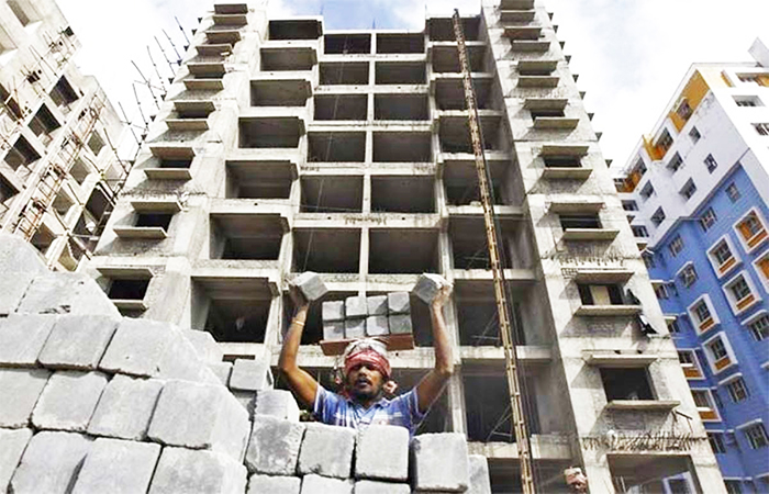
Hyderabad Metro Rail is a Public-Private-Partnership Project, that is being implemented through a special purpose vehicle (SPV) – “L&T Metro Rail (Hyderabad) Limited” – part of L&T Group Company. It is being executed on a design, build, finance, operate and transfer (DBFOT) basis with an investment in excess of Rs.16,000cr, generating a 10,000 plus -direct employment during construction period, and 3,000 post commissioning. Indirect employment to vendors and others are around 5,000 during construction period and around 100000 after commissioning including the18.5 million sft of Transit Oriented Development. The concession period for the project is initially for 35years, which is extendable further by 25 years.
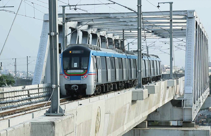
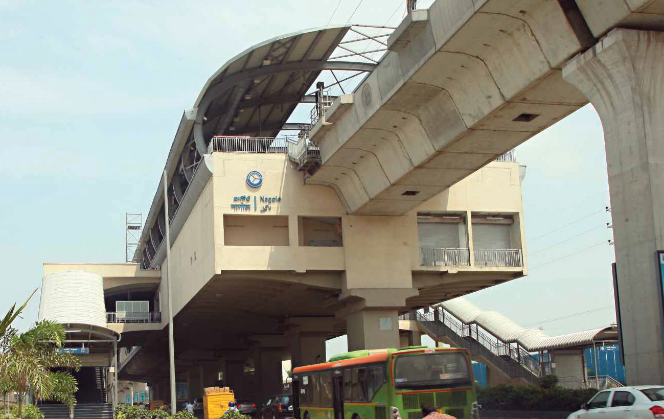
The Hyderabad Metro Rail Network covers a total distance of 71.16km and the Metro includes ultra-modern stations with state-of-the-art depots and complete infrastructure. L&T Metro has engaged world-class consultants, reputed contractors / vendors for construction of various Metro systems.
This project also has an opportunity of 18.5 million square feet of Transit- Oriented Development (TOD) in the earmarked (P&C) areas and depots.
Traffic Studies conducted by L&T Ramboll
Benchmarked against independent Traffic studies of other consultants
Parking & Circulation Area (6mn Sq. ft.), Depots (12.5 mn Sq. ft.) & Retail area in stations (20% of floor area of each Station)
M/s Mckinsey commissioned has undertaken a value enhancement study for TOD
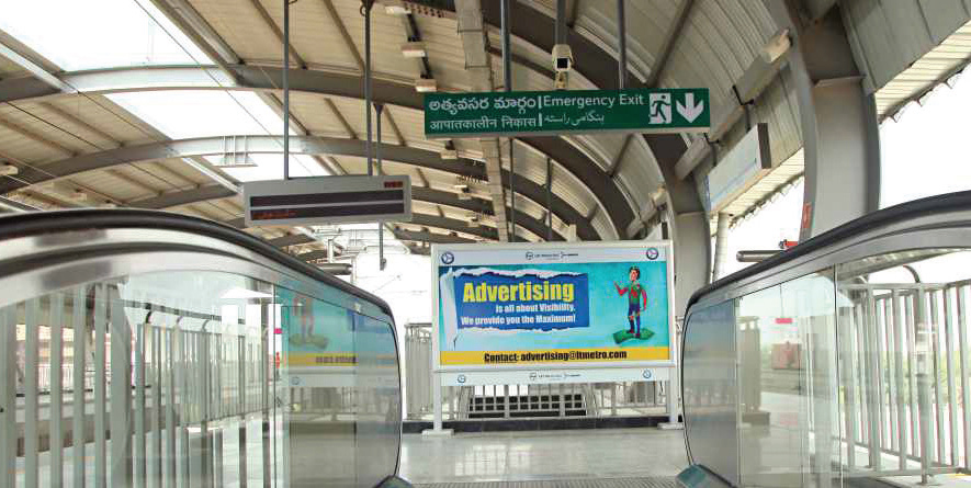
Advertisements – at stations, viaduct, in train, co-branding etc.
Parking – Provided at parking and circulation areas and depots
Specialty of the Project
Some “Firsts” in this Project are highlighted below:
Largest Metro Project in the world to be developed in PPP format
First Integrated Metro + Transit Oriented Development Project = Seamless Commute.
It is also the largest Single Urban Development Project in India
This project is being implemented not as a simple mass transit system, but as an Urban Redesign Concept with emphasis on last mile connectivity, room for cycling and other non-motorized transport, pedestrian facilities, green areas and public spaces with an eye on aesthetics
The Government is taking initiatives to make this project as a model for multi-modal interchanges
Financial closure achieved within 180 days of signing the concessionaire agreement
All the 3 main rail terminals, 8 important Bus depots / stations, and 6 MMTS (Local rail) stations are being integrated with the Metro Rail
Communication Based Train Control System is first time introduced in Indian Metro rail system as a signalling system, which can accommodate much greater frequency of train traffic
Innovative design for Stations – Spine & Wing arrangement – This reduces the land acquisition / property clearance near stations
Operator in place at a very early stage; O&M inputs into Project System design
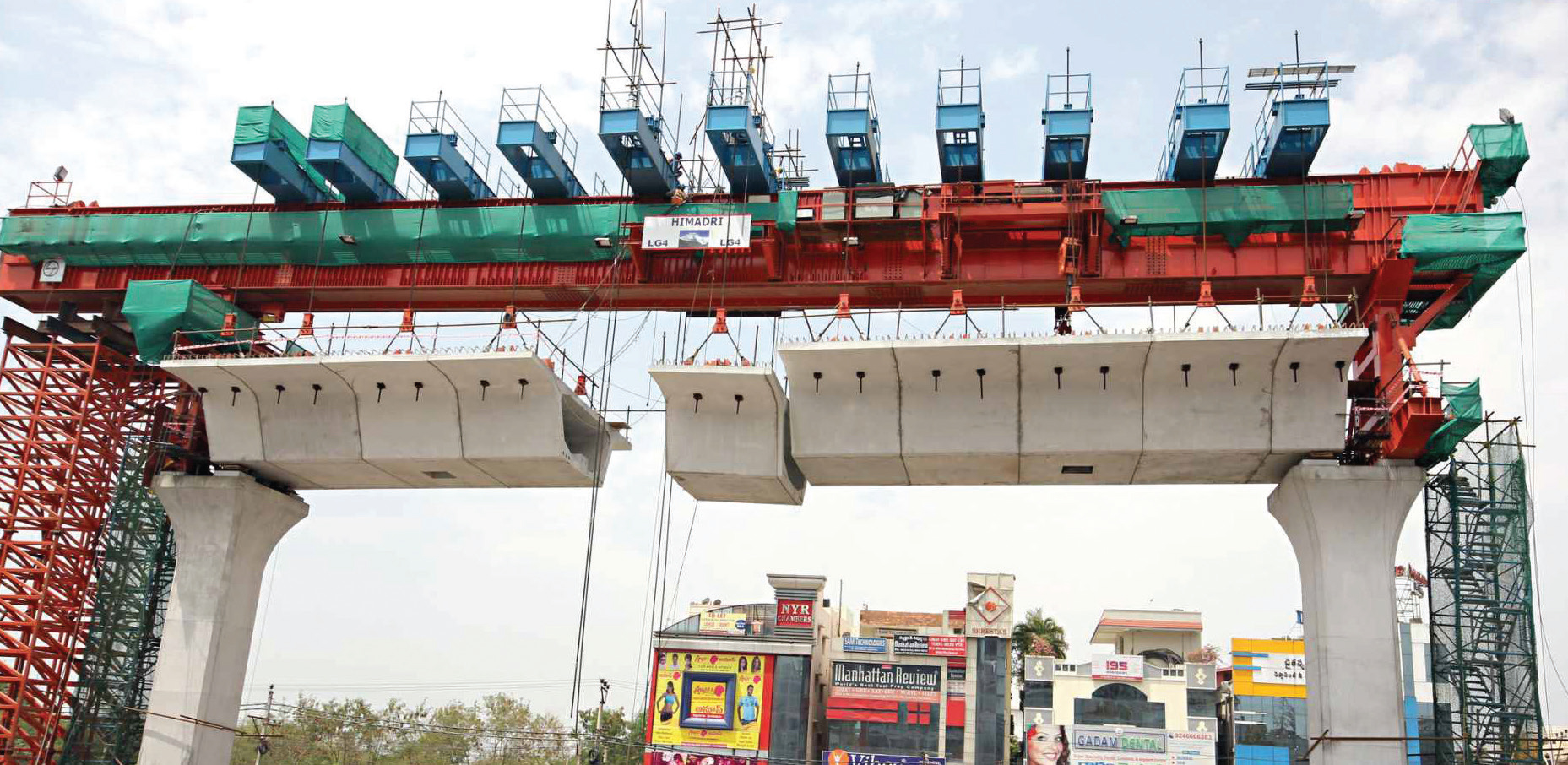
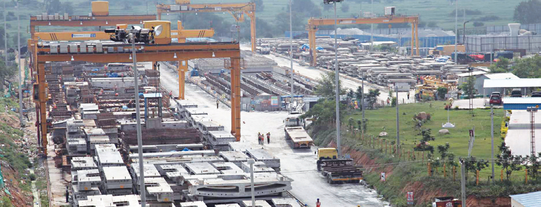
2 Largest Pre-cast yards in urban areas
Section of 30km inaugurated by Hon’ble Prime Minister of India on 28th November 2017. Operations underway since then.
Work in full swing on the remaining stretches to complete the same soon.
Substructure & Foundations
Piers are columns, which provide vertical support to the viaducts
Square or rectangular piers used with pier cap flares of required width at the top.
Foundations: majority of foundations are shallow open foundation with CLSM (Controlled low strength material) cast below foundation raft in case of inadequate bearing capacity of soil at 2.5 m level BGL (below ground level). In other cases, pile foundations of end bearing type with pile diameter ranging from 800 mm to 1000 mm have been used.
Bearings
These are the elements, which take the axial loads of the viaducts and all the equipment above it. Generally, neoprene bearings in combination with seismic arrestors are used to take care of all the vibrations. For special/obligatory span POT/PTFE and spherical knuckle bearings are used. Special stability checks carried out on superstructures for sharp curves (Min Radii of Curvature 128 m).
Viaducts/Superstructures
Viaducts are horizontal platforms over which the train runs. These viaducts are basically segmental precast post-tensioned box girders joined to span between two piers with the help of launching girders. Special/obligatory spans are either cast-in-situ or precast (3-span continuous or simply supported). The viaducts are accompanied by RCC parapets on top to support the signalling equipment and overhead masts. Noise barriers are provided on parapets in sensitive areas. The entire structure has a Design basis report (DBR), which was prepared with the knowledge of all stakeholders and has been RDSO/MoR approved.
Railway over Bridge (ROB)
There are 8 ROBs where Metro viaducts will be crossing the Indian Railways lines. The ROB structures are being designed by M/s Ramboll as Detailed Design Consultants (DDC), checked and approved by M/s Aecom – Feedback Infra on behalf of LTMRHL, approved by independent engineer (I.E) M/s Louis Berger Company on behalf of HMRL and finally proof checked by RITES on behalf of South Central Railways.
Oliphenta RoB
Amongst all the 8 Metro RoBs, Oliphenta Bridge construction is the toughest and an engineering feat.
It is located next to the Secunderabad Railway station, which is a very busy station and works round the clock
Since this is a double elevation RoB over an already existing elevated RoB, with a view to accommodate the future double-decker trains of Indian Railways, it is being built at a height of about 60 feet from road level.
It has the longest obligatory (main) span of 272 feet to accommodate the 8 existing and 5 future railway tracks. This means this Metro RoB is being built at a height of 60feet and without any middle support for 272 feet.
As the Metro alignment is in a steep curvature coming from Mettuguda side (a curve of 128m radius), the width of the steel bridge had to be increased to accommodate the Metro tracks with steep curvature.
The entire steel bridge weighing about 1100 tons made of special high-grade steel was first manufactured and assembled at a factory in Ghaziabad (near Delhi) simulating the site conditions of Oliphenta location and later dismantled piece by piece and brought to Secunderabad for reassembling.
The high strength steel truss structure elements are joined together with the support of these steel plates by using HSFG (High Strength Friction Grip) bolts. The assembling of these elements with absolute precision has been done on a one-acre site of railways near Oliphenta temporarily taken on lease.
This precision bolting and welding at a height of 60 feet at the bottom level of the bridge and at about 90 feet (top level of the bridge) can be done only by specialized workers under the supervision of bridge engineering experts. Since conventional bridge bearings cannot take care of the large longitudinal and lateral forces induced by a large span bridge, special “spherical bearings” which are the latest in bridge engineering are being used.
The total number of HSFG bolts used are about 65,000 and they are supported by Direct Tension Indicator (DTI) washers for splicing (bonding) the joints.
Station Design
Balanced cantilever structural system adopted for metro stations, is a unique one. It provides several advantages to the city during construction as well as after construction. Each station is having three levels, The Street Level, the Concourse Level and the Platform Level.
Concourse level is made up of pre-cast segmental post tensioned spine girder with end segments supported on bearings placed over pier cap. Precast post tensioned wings are attached on either side of the spine girder ensuring the service requirements.
Platform structure comprises of cast-in-situ slab laid over longitudinal precast pre-tensioned secondary beams. These secondary beams supported on cast-in-situ post tensioned concrete arms as primary beams. Roof is supported by a portal frame steel structure with metallic corrugated sheet.
The station pier in the road median is designed to support the track structure, platform structure and concourse level structure. The station piers are located at the central median of road and the station is cantilevered on the single pier, thereby avoiding any structural support from the shoulders of the road. The station box is proportioned to suit even for narrow streets of the city. Pier centres (spans) are maintained in such a way to achieve necessary road clearance (5.5m) and to meet the rail level requirements while carrying the station and viaduct loads. Each span between any two piers are independent and kept separate by providing expansion joints.
Entry-exit structures are located on either end of the road to facilitate easy approach for the passengers. Stations are designed considering the evacuation criteria prescribed as per NFPA 130 standard and barrier free design. All relevant standards such as BIS, IRS-CBC and BS codes have been adopted.
The Indian Green Building Council (IGBC) has launched IGBC Green Mass Rapid Transit System (MRTS) rating, to encourage green concepts in the design, construction & operation of all new Rail based MRTS projects. The rating system helps to address national priorities like conserving natural resources, demand side energy & water efficiency, adoption of renewable energy, management of waste and commuter health & comfort.
Stage I &II of L&T Metro Rail (Hyderabad) Limited has been awarded with the prestigious IGBC Platinum Rating for its 17 elevated stations, the highest accomplishment for any project. LTMRHL’s technical innovations of adoption of the spine & wing concept, the hump at the station platform level, regenerative braking in rolling stocks and greening of median areas below viaduct has led to the spread and growth of green metro rail movement in the country. LTMRHL will be the trendsetter for the upcoming metro rail projects all over India to incorporate some of the initiatives.
Concrete Used
Temperature controlled concrete was used in all the structures. The automatic concrete batching plants were connected to chilling plants, which cool down water to a temperature of 50°C. The concrete was transported via transit mixers which were wrapped with multi- layered hessian cloths to keep the drum cooled, during the transit.
Concrete laying was predominantly done during the night hours, to protect from hot weather and avoid probable plastic shrinkage cracks.
The mix design of concrete was carried out to achieve a higher workability of 200±25mm by slump test at the placing location without any bleeding and segregation. Poly carboxylate based chemical admixtures were used for this purpose. These admixtures have been blended to retain the workability up to five hours.
Construction Practices
The segments and the beams are being precast in a yard. The precast yard is located at Uppal, equipped with overhead gantries and plant for readymade reinforcement steel. The precast yard is bifurcated into many smaller units, called as ‘reinforcement yard’, ‘casting yard’, ‘curing yard’ and ‘stacking yard’.
Standard formwork was fabricated with steel. The bed that receives the segment precast was survey checked and adjusted to alignment and profile of the station. Reinforcement was tied on a standard zig, lifted and placed on the above bed. The side shutters and inside forms were placed, HDPE sheaths were placed and aligned, and the mould is ready to receive the concrete.
Concrete in the segment/beam mould was placed in two methods, one by ‘boom placer’ and the other by the ‘concrete crane bucket’ hung through gantries.
‘Concrete Boom Placers’ were used to place the concrete at its position. These were helping not only to reach higher heights but minimize segregation of mix even at longer travels and/or higher reaches. The concrete in the piers was placed by tremie method to avoid segregation due to higher height of fall.
The concrete in pier was compacted using high frequency vibrators with longer trunks/cables. Mould vibrators were also used for precast segments.
The precast girders/segments/wings are transported using long body trailers and erected in situ using the launching gantries. Each span receives 8-10 of the precast segments based on the span configuration (13m or 17m). After completion of post-tensioning activity joining the segments in a span, the span lowered on to the elastomeric bearing placed atop the pier cap.
The precast pre-tensioned beams meant for the platform, transported using trailers, are erected insitu using crawler mounted cranes or chariot cranes installed on the rail track on viaduct. Each span receives three beams on each side of Left Hand Side and Right- Hand Side platforms.
The Entry-Exit to Station on all its four ends/sides, Underground sumps, Escalator and Lift supporting structure, Staircases made of reinforcement concrete are cast-in situ as per approved ‘Good for Construction (GPC)’ drawings.
Special Machineries
Apart from using Launching Girders/Gantries, ‘Chariot Crane’ has been used. Chariot Crane is a 75MT crane on steel wheels. Above the plinth beam that is meant for installing rails for train to move, temporary rails have been installed and chariot crane deployed. This crane was used for erection of pre-cast pre-tensioned beams for `station platform.
Safety Practices
Introduced Designer’s certification of temporary structures prior to loading/use, to conform formwork standards as per the scheme requirements.
New colour coding of helmets was introduced to newly joined employees. This will enable easy identification of new employee till he/she gets familiar with the system, guided/supported by the senior employees, to prevent unsafe acts.
Height pass was introduced to all the people involved in working at height, to familiarize with dos and don’ts.
Introduced modular frames instead of guard rail at platform level to prevent fall of material.
Introduction of rear cameras to tele-handlers for effective reversing of vehicle, targeting zero harm.
Introduction of blue-tooth ear-in speakers to all operators/ drivers to stay focused while driving
External Station Structure
The balanced cantilever structural system typically adopted for metro stations is a unique one. It provides several advantages to the city during as well as after construction. The station piers are located at the central median and the station is cantilevered on the single column, thereby avoiding any structural support at the side medians. Following advantages are achieved by this system:
Sleek station box (20m) suitable for narrow streets of the city
No obstruction to the surrounding properties
Minimum impact on site lines for branching bye-lanes and roads
No tunnel effect i.e. adequate ventilation and lighting for road users below
Delinking of station box construction with entry structure construction
Passenger Safety
The stations are designed to meet evacuation and fire separation norms as per internationally accepted standard for Fixed Guide Way Transit and Passenger Rail System, National Fire Prevention Association (NFPA-130). Fire detection and suppression provisions are planned in accordance with Indian National Building Code. Essential power back-up is provided for operational purposes as per relevant codes.
Differently-abled Friendly
Ticket vending machines are provided to aid the passengers with speech impairments. Wide automatic fare gates are provided for passengers on wheelchair. Direction to all commuter facilities like ticketing, washroom, lifts, staircase, train door, customer service, etc. has been provided through tactile flooring for visually impaired passengers. There are designated wheelchair spaces in the first and last car of the trains. Five per cent of seats are designated for the physically challenged passengers. Fixed and dynamic lit signages within the trains are provided to guide hearing impaired passengers. Announcements are made in the train to aid those who might be unable to see or read the information being shown on the signage.
Eco-friendly
Energy efficient features are incorporated in station design. The stations are generally located on hump which means reduced power requirement to decelerate or accelerate for an approaching or departing train respectively. The stations are open buildings with minimum external walls in public areas, reducing lighting requirements during day time and providing ample ventilation. LED lighting systems with reduced power requirements and solar panels to capture alternative power, etc are installed in the station.
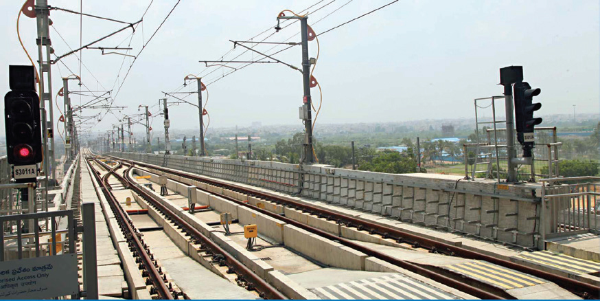
Trackwork
The entire mainline of The Metro Project has ballast-less track, whereas tracks in depots are ballasted and special tracks. The primary reason of adopting ballast-less track technology is lower maintenance requirement, which suits our time constraints (non-revenue hours available for maintenance work). The permanent way consists of rails of profile 60 E 1 Head Hardened Gr.1080 for complete main line and rails of profile 60 E 1 Normal Rails Gr.880 for depots which shall be 18 m long. The rails manufacturing and testing will be done as per IRS – T- 12, 2009. Restraining rails of profile 33 C1, grade 880 of 13 m length shall be provided for all curves of radius less than 190 m.
Fastening system 336 is being adopted for ballast-less track in this project. The fasteners are spaced at 650mm c/c on viaduct and ramp with 1 in 40 rail inclination. The track in the depots has been laid on ballasted track and special track with Standard Gauge Mono block PSC Sleepers with the spacing at 600mm c/c sleeper using ERC MK III fastening system and GFN Liners of indigenous make and 65mm stone ballast with minimum cushion of 250mm under the sleepers. The cushion is 300mm for test track. Portion of depot track has also been laid as embedded track with special base plates and on plinth with ballast-less fastenings to suit the requirement. All the turnouts to be negotiated are with 1 in 40 rail inclination. 1 in 9 switches of radius 300 and 190 for the main line and 1 in 7 switches of radius 190 in the depot with Zu 60 profile (thick web) are used. All the running rails are continuously welded by Flash Butt Welding/Alumino Thermic Welding processes. The track on Main Line has been laid on plinth type ballast less track with rails discretely supported by ballast less fastenings on Concrete plinths of M35 grade.
Sustainability
Green construction practices have been followed such as solid waste management, rainwater harvesting, pollution control, environmental protection:
Metro-the efficient eco-friendly time saving initiative has made luxury economical. Go-green initiatives have been the crux of the project
Metro rail is one of the cleanest and greenest modes of transport, which helps in reducing the Green House Gas (GHG) emission and Carbon Foot Prints in the City of Hyderabad. As part of this, we have initiated ‘Clean Development Mechanism –CDM’ registration process with United Nations Framework Convention on Climate Change (UNFCCC) along with our Ministry of Environment & Forests
We anticipate generating more than 3.5 million CERs though our project (our project is already appearing in the UNFCCC website). The carbon emission reduction will be both due to modal shift from the conventional modes of transport to metro as well as due to regenerative braking technology. The project is likely to bring a vast modal shift to metro and provide the people of Hyderabad a comfortable, air-conditioned, economical and yet green transport. Anticipated reduction of 3.5 lakh metric tons of CO2 per year from the atmosphere due to people using electrically operated trains thereby enhancing green environment.
Dr. Manchikanti Srinivas
Professor
Department of Civil Engineering,
Gayatri Vidya Parishad College of Engineering (Autonomous)
Visakhapatnam
Vedangi Mani Raju
M.Tech (Infrastr. Engg. & Mgmt.) Student
Department of Civil Engineering,
Gayatri Vidya Parishad College of Engineering (Autonomous)
Visakhapatnam
The desires of the people are changing day after day and the living standards are also improving due to the increased purchasing power. Hence people are desirous of a more comfortable life, which includes a comfortable lifestyle when it comes to housing and the allied facilities [10]. Therefore, people can now afford to buy and live-in satellite townships, as there are many advantages such townships offer. This paper presents a master plan of the proposed Satellite Township which is developed based on an exhaustive study of various master plans of well-developed cities like Pune, Chandigarh etc.
Residential areas are developed either as (a) Plotted Development or (b) Group Housing Development. The density pattern (high density, medium density, and low density) is followed for working out the pattern of development with respect to the size of the plot, number of dwelling units in each plot, setbacks, Floor Area Ratio (FAR) and the number of storeys/height of the building [5]. The municipal and social infrastructure as per the norms and standards specified in the master plan are provided. The various sites or plots required for social and municipal infrastructure are indicated in the layout plans. The development norms for different users or activities and on different sizes of plots apply for sanctioning of the plans based on the TCPO (IS: 8888-1993) manual [8]. These are based on development control rules applicable to the city or town. After a thorough study of the amenities provided in various master plans, it is proposed to provide better amenities in the proposed Satellite Township.
Generally, the minimum plot size is 30 sq.m. However, the plot size may vary depending upon the type of the housing needed for a particular city, based on the general affordability of the people. The size of the plot would also depend on the number of dwelling units to be permitted on each plot. The proposed township is planned in Visakhapatnam, which has an undulating terrain. As per Floor Area Ratio (FAR) the size of standard dwelling units are fixed based on the density pattern given in the development plan, taking into consideration a population of 4.5 persons per dwelling unit [5].
Details Of Residential Complex In Satellite Township
The total area of all the 2BHK and 3BHK flats put together is 5.44 acres, which constitutes 13.6% of the entire Satellite Township (of area = 40 acres).
2BHK
All 2BHK flats are provided with amenities like:
One master bedroom with attached toilet
Children bedroom
Kitchen
Pooja room
Dining hall
Store room
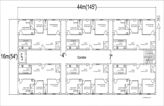
Fig. 1: CAD Plan of a 2BHK Dwelling Unit
All the 2BHK flats are exclusively constructed in a block and there are 15 floors in a block.
Dimensions of one 2BHK flat:
Length (L) = 13.87m
Width (B) = 6.7m
Dwelling units:
In one 2BHK block there
are 15 floors.
Each floor has 6 flats
Total number of flats =
15 x 6 = 90 Flats
Total number of dwelling units in 6 clusters or blocks = 90 Flats x 6 Blocks = 540 Flats
Number of people accommodated = 540 x 4.5 persons = 2,430 people (Assuming 4.5 persons per flat)
Dimensions of one 3BHK flat:
Length (L) = 14.7m
Width (B) = 11.84m
Bill Of Quantities i) For a 2BHK flat:
Up to plinth beam cost = Rs. 9,68,072/-
One flat cost = 19,62,782/-
Total cost = Plinth beam + Flat cost = 9,68,072 + 19,62,782 = Rs. 29,30,854/-
Ground floor = 6 Flats = 6 x 19,62,782 = Rs. 1,17,76,692/-
1 Block = 15 Floors = 15 x 1,17,76,692 = Rs. 17,66,50,380/-
6 Blocks= 6 x 17,66,50,380 = Rs. 1,05,99,02,280/-
ii) For a 3BHK Flat
Up to plinth beam cost = Rs. 9,79,676/-
One flat cost = Rs. 21,01,030/-
Total cost = Plinth beam + Flat cost = 9,79,676 + 21,01,030 = Rs. 30,80,706/-
Ground floor = 4 Flats = 4 x21,01,030 = Rs. 84,04,120/-
1 Block = 15 Floors = 15 x 84,04,120 = Rs. 12,60,61,800/-
8 Blocks = 8 x 12,60,61,800 = Rs. 100,84,94,400/-
Conclusions
Optimal land-use plan is developed considering the models used at various places for similar projects in the country.
After a detailed estimate, the proposed cost of a 2BHK to the buyer will be Rs. 40 lakhs and 3BHK will cost 60 lakhs. These costs are considered to be economical considering the prevailing market prices.
The developer(s) will earn an assured profit of 25% after executing this project.
It is a Greenfield project and care has been taken to ensure that the environment is not affected due to this project coming up.
Fig. 4: CAD Plan of a 3BHK Block
References
Deepali J.Chavan., Ravindra H.Sarnaik., Self-Sustainable Township, International Journal of Innovation in Engineering and Technology (IJIET), Vol. 2, pp. 387-440, Feb 2013.
Dutta, B.N., Estimating and Costing in Civil Engineering Theory and Practice, USB Publishers Distributors (P) Ltd., 27th Ed., 2013.
IS SP: 7 Energy conservation building code (ECBC), 2005.
Kumara Swamy, N., Kameswara Rao, A., Building Planning and Drawing, Charotar Publishing House Pvt. Ltd, 7th Ed., 2014.
National Building Code of India, 2005
Seetharaman, S., Construction Engineering and Management, Umesh Publications, 4th Ed., 1999.
Special township policy, 2004, Govt. of India
IS 8888-1 (1993): Guide for requirements of low income housing, Part 1: Urban areas [CED 51: Planning, Housing and pre-fabricated construction]
http://articles.economictimes.indiatimes.com/keyword/satellite-towns accessed on September 3, 2015.
http://articles.economictimes.indiatimes.com/keyword/satellite-towns/featured/3 accessed on September 3, 2015.
http://www.businessstandard.com/article/economy-policy/tamil-nadu-plan-rs-4-500-crore-satellitetownship-114071101037-1.html accessed on September 3, 2015.
http://www.researchgate.net/…/2708949 30-evolution-of-satellite-township-development-in-punea-case-study accessed on September 2, 2015.
Dr. Ramesh Kumar
Research Scholar
Jawaharlal Nehru Technological University
Kakinada, Andhra Pradesh
Dr. P. Udaya Bhaskar
Chairman
Andhra Pradesh Public Service Commission
Vijayawada, Andhra Pradesh
As cities in developing world are under demographic transition and the forces of economic liberalization taking grip over them, they are engulfed by a number of problems. The pressures of population growth and globalization, however, demand these cities to be more competitive and their infrastructure should be responsive to promote welfare of its population. Unfortunately, most cities are not well equipped to tackle some of these problems like water scarcity, slums management, urban waste management, sewage, transportation etc., which led to the failure of local government institutions in the provision of public goods and services in an efficient and effective manner. Such failures provide an institutional vacuum in making the service delivery process efficient and responsive. Non-profit networks can emerge in such settings by forging partnerships between the stakeholders, thereby, steering appropriate governance structures.
Urbanization is an integral part of the process of economic growth. As in most countries, India’s towns and cities make a major contribution to the country’s economy. With less than 1/3 of India’s people, its urban areas generate over 2/3 of the country’s GDP and account for 90% of government revenues.
Urbanization in India has expanded rapidly as increasing numbers of people migrate to towns and cities in search of economic opportunity. Slums now account for 1/4 of all urban housing. In Mumbai, for instance, more than half the population lives in slums, many of which are situated near employment centers in the heart of town, unlike in most other developing countries.
Meeting the needs of India’s soaring urban populations is and will therefore continue to be a strategic policy matter. Critical issues that need to be addressed are:
Poor local governance.
Weak finances.
Inappropriate planning that leads to high costs of housing and office space; in some Indian cities these costs are among the highest in the world.
Critical infrastructure shortages and major service deficiencies that include erratic water and power supply, and woefully inadequate transportation systems.
Rapidly deteriorating environment.
Challenges
Planning
Many urban governments lack a modern planning framework.
The multiplicity of local bodies obstructs efficient planning and land use.
Rigid master plans and restrictive zoning regulations limit the land available for building, constricting cities’ abilities to grow in accordance with changing needs.
Housing
Building regulations that limit urban density – such as floor space indexes – reduce the number of houses available, thereby pushing up property prices.
Outdated rent control regulations reduce the number of houses available on rent – a critical option for the poor.
Poor access to micro finance and mortgage finance limit the ability of low income groups to buy or improve their homes.
Policy, planning and regulation deficiencies lead to a proliferation of slums.
Weak finances of urban local bodies and service providers leave them unable to expand the trunk infrastructure that housing developers need to develop new sites.
A Slum Housing Colony in Mumbai
Service Delivery
Most services are delivered by city governments with unclear lines of accountability.
There is a strong bias towards adding physical infrastructure rather than providing financially and environmentally sustainable services.
Service providers are unable to recover operations and maintenance costs and depend on the government for finance.
Independent regulatory authorities that set tariffs, decide on subsidies and enforce service quality are generally absent.
Infrastructure
Most urban bodies do not generate the revenues needed to renew infrastructure, nor do they have the creditworthiness to access capital markets for funds.
Urban transport planning needs to be more holistic – there is a focus on moving vehicles rather than meeting the needs of the large numbers of people who walk or ride bicycles in India’s towns and cities.
Environment
The deteriorating urban environment is taking a toll on people’s health and productivity and diminishing their quality of life.
In the past, urbanisation and its concomitant challenges commanded low priority in national political discourse. Recently, however, the economic and demographic rise of cities in many parts of the country, especially Southern and Western India, and the National Capital Region, are drawing greater attention. This is likely to rise further in the coming years as urbanisation mounts.
The World Bank will look to support policy reform in critical areas such as land use planning and municipal finance, as well as institutional reform. It will work with all three tiers of government in designing programs to address slums, housing and urban infrastructure requirements.
Conclusion
The phenomena of urbanization, globalization and liberalisation are increasing pressure on service delivery in the cities of developing countries that are engulfed by vast number of problems. Unfortunately, most of the cities are ill equipped to tackle the problems and pressures because either they gave inadequate thought about the trajectories of city growth or because they did not plan and allocate resources to do it; even otherwise, there are inefficiencies built-in through traditional designs of institutions of service delivery made on political and bureaucratic forces. This is leading to government failures in service delivery, which can be addressed by institutional innovations under partnership mode (apart from governance reforms) to steer urban governance in right direction. However, policy reforms are also needed so that right kinds of incentives prevail for nurturing new institutions (Virmani 2005).
Better planning, reducing conflict with environment, best water management systems, good governance, digitalisation of land records, eco-friendly construction methods will improve living standards of the urban population.
References
Virmani, A. (2005), ‘Institutions, Governance and Policy Reform: A Framework for Analysis’ Economic and Political Weekly of India XXXX(22).
Rajeev Gupta
Business Head
ECMAS Construction Chemicals Pvt. Ltd.
Hyderabad
Concrete is usually made of water, cement, admixtures and aggregates. Generally, the quantity of water added to the mix is greater with respect to the stoichiometric value which is essential to completely hydrate the cement. Mix water cannot be reduced to the theoretical quantity required even if superplasticisers are used. During concrete setting or hardening, the extra water that was used while making the concrete would eventually evaporate. The evaporation of the excess water isn’t a major problem in itself provided the whole process takes place in controlled conditions (at 20°C and 90% relative humidity).
The water evaporation speed primarily relies on factors like wind speed, relative humidity, ambient and concrete temperature. Usually, the condition of concrete casting is a lot different from the ideal condition that has been shown above. In that case, the water evaporation leads to the formation of micro fissures which collectively degenerates and forms cracks and macro fissures.
Cracking issues and joint failures usually bother the concrete floor and pavement owners due to the expensive repairs. A negative perception is usually associated with cracks regarding its longevity, quality and serviceability of pavements or concrete floors. Cracks are usually seen as aesthetic issues but it can create major disputes between consultants, clients and contractors resulting in cost overruns and delay in work process.
Conventional Steel Reinforcement For Concrete
Conventionally, standardized welded steel fabric in the forms of bars and meshes, has been used as reinforcement in various applications such as concrete floors, pavements, steel deck slabs, bridge decks, etc. for many years. Steel is primarily necessary to carry the loads after the concrete cracks and to hold together broken pieces of concrete. Steel in the forms of bars and meshes primarily functions as two-dimensional reinforcement. However, some structural concrete applications require a three-dimensional approach to reinforcement. Further, the use of steel in various forms, including steel fibers, has other problems related to either in-place performance or handling and placement including corrosion. Corrosion of reinforcing steel is a major concern as it affects the long-term durability and performance of any steel-reinforced concrete application. This corrosion concern is even more important in shotcrete applications that are constructed in a marine or water environment, or in an underground structure which are mostly wet. Equally important concern is ensuring the minimum necessary concrete cover for the steel mesh and rebar to protect it from corrosion and other chemical contaminants.
The reinforcement of mesh and steel rebar need to be spliced, bent, cut and attached to the project substrate, the entire process is laborious. In addition to this there are also chances of human injury when it comes to handling the steels. The availability issues and costing are also concerning factors regarding all forms of steels- mesh, bar and fibers.
Various fiber-reinforcing materials are available nowadays but structural applications of fiber-reinforced concrete are mainly made of steel fibers. But in recent years, new breeds of structural synthetic equivalents are proving their usefulness. Lighter weight, lower abrasion and better structural performance are making synthetic reinforcement an economic alternative.
How Do Fibers Work In Plastic Stage Of Concrete?
For architectural and aesthetic concrete products and for prevention of early age cracking Micro Synthetic fibers are generally used while Macro Synthetic Structural fibers or Steel fibers are mainly used to control properties of concrete in the hardened stage such as post-crack flexural strength, abrasion resistance, impact resistance and shatter resistance of concrete, etc.
Early age concrete shrinkage causes weak planes and results in the formation of cracks, because the stresses developed in the concrete exceeds its tensile strength at that specific time. The growth of these micro shrinkage cracks can be inhibited by the mechanical blocking action of both synthetic and steel fibers. The internal support system of the fibers inhibits the formation of plastic settlement cracks. The uniform distribution of fibers throughout the concrete discourages the development of large capillaries, caused by bleed water migration to the surface. Fibers thus lower the permeability of concrete through the combination of plastic crack reduction and reduced bleeding characteristics.
ECMAS EXF 54 is an easy-to-finish, blended fiber, made of 100% virgin polyolefin consisting of a twisted bundle non-fibrillating monofilament and a fibrillating network fiber, yielding a high-performance concrete reinforcement system. ECMAS EXF 54 disperses uniformly in the entire concrete mass and it helps to reduce plastic and hardened concrete shrinkage, improve impact strength, and increase fatigue resistance and concrete toughness. ECMAS EXF 54 is non-corrosive, non-magnetic, and 100% alkali-proof offers long-term durability, structural enhancements. They have a high tensile strength and a relatively high modulus of elasticity.
To maximize resistance to pull-out and post crack behavior, ECMAS EXF 54 Hybrid Macro Fiber involves a blend of two different fiber types & shapes:
A standard fibrillated polypropylene fiber to reduce and control shrinkage and temperature cracking.
A very heavy-duty twisted-bundle monofilament fiber made of a strong synthetic copolymer with embossed surface, to increase load-transfer and post-crack performance. This pre-blended fiber is typically used in long lengths (54 mm) and in high dosages to affect a higher replacement level of reinforcing steel than standard synthetic micro fibers.
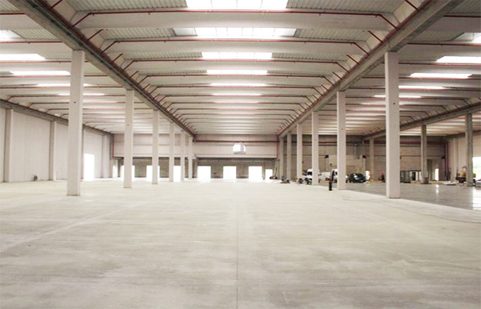
ECMAS EXF 54 is mainly used for performance concrete applications such as industrial & warehouse floors, concrete pavements, steel deck slabs, bridge decks, shotcrete, loading docks, light precast products – anywhere when steel reinforcement reduction or replacement is the objective.
Concrete Floors, Pavements & Parking Lots
The concrete grade slab present in the industrial warehouse factories has two essential functions: firstly, it has to sustain the operational goods from the loaded racking system, they directly store the goods on the floor, fork-lift truck wheel loads and are responsible for transferring the same to the supporting soil. The job is done without any structural failures or disturbing the settlements. Secondly, it provides a good wearing surface on which the functions in the facility can be carried out with safety and efficiency. Both the functions achieved by the industrial floor slabs is the main reason behind the success of modern commercial advantages.
The primary purpose of industrial floors is to provide sufficient reinforcement to control the amount and size of cracks to achieve a consistent level with the appropriate use of the floor.
ECMAS EXF 54 Fiber Reinforced Concrete helps reduce the width of cracks, and permits the replacement of conventional steel reinforcement. This process is more prone to corrosion which will require a lot of maintenance of the floor in the near future. But when you use FRC, these cracks tighten up and prevent moisture and chlorides from entering the floor and penetrating down to the basic level of reinforcing. It also helps to bridge areas where there was no reinforcing present in the past. Hence, it reduces chipping, spalling and eliminates the formation of potholes and section losses.
By reducing the joint widths and frequency, and adding EXF 54 fiber reinforcement, it is anticipated that the concrete pavement will last much longer than a traditional concrete parking lot.
Composite Metal Deck Slabs
A typical metal deck consists of a corrugated steel sheet with a concrete topping, with the sheet serving as both a permanent form and as the principal reinforcement for the slab. Historically, welded wire mesh fabric has been used as a secondary (non- structural) reinforcement to control rather than prevent concrete cracks.
Synthetic Structural fibers have become a well-recognized, cost effective, and acceptable reinforcement for slab on metal deck applications. But beyond the cost-savings and long-term reduction or prevention of cracking is a more fundamental reason to choose synthetic fiber reinforcement:
The use of conventional steel reinforcement in slab on deck applications brings a host of ease of use and proper placement concerns. For the welded wire fabric to be effective in controlling this shrinkage/temperature cracking, it must be placed within the top-third of the concrete cross-section, a process that is quite challenging in execution. The simple transport of mesh rolls or sheets to upper-level deck projects is difficult and labor-intensive.
ECMAS EXF 54 fiber reinforcement system provides great time and labor savings as this is simply added to the concrete mix as an ingredient, in addition to the uniform three-dimensional reinforcement coverage it provides throughout the concrete deck matrix compared with single-plane steel.
ECMAS EXF 54 Synthetic fibers meet and exceed established measurement standards and building codes set forth by Underwriters Laboratories (UL), American Society of Testing and Materials (ASTM) and the American Concrete Institute (ACI).
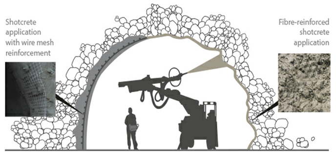
Shotcrete
Concrete is pumped through a hose and projected at high velocity onto the desired surface. Traditionally, welded wire fabric (WWF) is used as temperature-shrinkage reinforcement in shotcrete applications. Sometimes, configuration to the substrate by the steel does not happen because the steel is too stiff, and excess shotcrete material is used to cover the steel. Lastly, applying shotcrete through the steel “obstruction” makes the shotcrete system performance very dependent on the operator skill to reduce shadowing. These placement and performance deficiencies of steel reinforcement served as further incentive to develop a level of synthetic fiber reinforcement that could serve as a viable alternative
As with slabs-on-ground, synthetic structural fiber reinforcement is an advantageous alternative, providing several technical, economic, and safety benefits as compared to traditional secondary, steel reinforcement including, but not limited to, temperature shrinkage crack resistance, crack-width control, impact and abrasion resistance, and spalling resistance. The long-term durability benefits far outweigh the often-questionable performance of wire mesh at a very competitive cost. EXF 54 Fiber-reinforced concrete with greater ductility allows it to deform under tensile stress, as well as greater energy absorption capacity despite cracking.
Compared with steel mesh reinforcements, ECMAS EXF 54 fiber reinforced shotcrete also has many other benefits, such as:
a greater homogeneity of the support structure
a more efficient rock section profile, allows for a uniform thickness and uniform density following the contours of the receiving face
offering simpler application logistics
fibers help reduce rebound (cost advantage) and improve compaction
Fire: In the event of fire accidents in tunnels, synthetic structural fibers prevents the hazardous phenomenon of “spalling”, that is, violent explosion of the concrete structure. During a fire, once fibers reach their melting temperature, they decompose without producing any harmful gases and transform the volume they occupied in the cement into a series of interconnected empty channels. These provide escape routes for heat and steam generated in the fire due to sudden boiling of interstitial water.
Precast Structures
Macro synthetic fiber concrete reinforcement is premixed with the concrete and delivered straight to the precast mould, eliminating the steel installation process. It helps achieving an increase in production output and total cost savings. It Eliminate the need for storage and installation of standard steel reinforcement in precast elements. Project experience has shown that structural synthetic fiber concrete reinforcement can increase precast production speeds up to 50%. Macro synthetic structural fibers are mixed throughout the entire structure, eliminating concrete cover requirements. In many cases this will allow for a reduction in element thickness and a reduction in weight. Also, many precast items are exposed to the corrosive environments but macro synthetic structural fiber concrete reinforcement will never rust and will continue to perform for the full life of the concrete.
Attention to Application of Structural Synthetic Fibers
The main reason why synthetic structural fibers are not quickly adopted and used commonly as there are no proper guidelines on how exactly they should be utilized. There are no prior references for the correct usage of synthetic structural fibers. It is essential to know the proper application of the same, like how to add, mix, place and how finishing, compaction and curing is done and what are its effects on concrete entities. The ECMAS EXF 54 macro fibers are usually added to the concrete and dry mixture before water is added during the final mixing process. The rate of dosage of EXF 54 Fiber depends on the specific applications and the appropriate properties. It varies between 1.2 to 3.5kg/m3 for maximum applications. To achieve perfect results, you need to be careful about the proper mixture done while mixing the design and batching procedure for EXF 54 Fiber. The placing of structural synthetic fibers is precisely the same as regular concrete. It would help if you made sure that the concrete is sufficiently compacted, which would lead to take out the paste to the surface and allow its perfect finishing. After compaction, an easy float is usually passed over the concrete to close up the surface. The moment the fiber reinforced concrete has been levelled, compacted and floated; it can sustain with proper concerning practice. Surface friction is required to achieve Anchorage across a crack to acquire the best functioning of structural synthetic fiber. Cracking due to plastic shrinkage and drying shrinkage of the concrete is avoided by this process. It also improves the properties of concrete, such as the toughness of cracks, flexibility, impact and fatigue resistance.
Conclusion
Use of Synthetic Structural Fiber Reinforcement in Concrete has been rapidly growing throughout the construction industry since clients, contractors and consultants have started to recognize its benefits in terms of enhanced performance, durability, safety and convenience; reduced construction time and labor costs. Fiber Reinforced Concrete (FRC) has been proven to reduce cracking, reduce crack widths and in some cases, allow for replacement of conventional steel reinforcement which can be more prone to corrosion, accelerating the need for future maintenance.
A Sofi
Associate Professor
Department of Structural and Geotechnical Engineering, School of Civil Engineering
VIT Vellore
Sanu Peter Thobiyas
M. Tech Structural Engineering
VIT Vellore
With time, it has been proven that the use of fibre reinforced concrete will fortify reinforced concrete structures’ structural performance. Fibre-reinforced concrete improves the mechanical and structural properties of concrete. Various fibres and natural, synthetic, glass, steel, and others are used to enhance mechanical property concrete. The manufacture of steel items is increasing, and the accumulation of waste steel fibre is negatively affecting the environment. Therefore, effective and economical methods to convert this waste material to a building material is necessary. Different experimental and mathematical studies were conducted to study the feasibility of the use of waste in concrete.
In the modern construction world, the efficiency and the quality of the concrete cannot be compromised. Thus, the concrete should meet the structure’s demands. The concrete’s main problem is its weak tensile and ductile property. Effective use of fibre can overcome this issue and form a modified concrete. As mentioned earlier, there are many kinds of fibres; mild steel fibre from lathe waste can also be included in it. The addition of fibre can modify the crack propagation and failure crack under loading.
Mainly failure in fibre reinforced concrete will occur due to failure in bonding between the fibre and the concrete. The existing studies show that the changes in concrete properties are directly linked to the shape, length, aspect ratio, amount of addition, etc.[1–5]. For the cases of mechanical properties, remarkable improvement in the tension, and flexural behaviour have been observed. Under the loading, after the formation of the crack, the fibre starts its function.
The objective of the fibre is to resist the propagation of the crack and prolong the failure load. It was observed that fibre-reinforced beam, even after the formation of the crack, the beam won’t fail, and the load will reach the peak value depending on fibre content[8,12,13]. Beyond peak value, applied load decreased due to the failure of fibre and stress transformation from bottom to top of the section. The fibre reinforcement shows an improvement in stress-strain behaviour also [24-26]. Normally, the ultimate strain of reinforced concrete is 0.0035. But under the case of FRC, the strain value is increased to 0.012 and 0.018 at 1.6% and 3% of the fibre. This is an improvement in strain corresponding to peak stress with an increase in fibre content.
It is evident that the steel fibre uplifts the concrete’s structural integrity, and the usage of the steel fibre in concrete can be implemented in the construction. Due to the increase in steel usage, the accumulation of steel scrap increased and caused a lot of environmental issues. Various researches have been conducted to study the use of waste fibre as an alternative to the manufactured steel fibre. Some studies support the use of the lathe scraps, and from there, improvements in the mechanical properties were observed [19 – 21]. The effective usage of the lathe scraps paves the way to the production of economic and modified concrete.
The current research looks into the change in mild steel fibre reinforced concrete’s mechanical property and compares it with conventional concrete. Mild steel fibres from lathe waste are used as a substitute for the manufactured steel fibre. Lathe wastes are added at various percentages (0.0%, 0.5%, 1.0%, 1.5%, and 2.0%) by weight of concrete. For the experimental studies, concrete cubes, cylinders and beams are cast. Cubes and cylinders are employed to determine the compressive strength, split tensile strength, stress-strain behaviour, and elasticity modulus. Flexural strength is studied by testing the concrete beam.
Material Characteristics
The study’s aim is to understand the change in the properties of lathe waste added fibre in the concrete. Lathe waste fibre of the same material collected from a mechanical workshop was used for testing. Mild steel fibres with spiral cross-section were selected as the fibres. For the analysis, the fibre volume was kept as a variant, and the length was kept constant. The changes in mechanical and durable properties of concrete due to the change in the fibre volume were studied. The materials used for the casting works are:
Cement: Ordinary Portland cement of grade 53 was used for the study. The initial and final setting time obtained was 30 minutes and 240 minutes. Cement has a specific gravity of 3.15 and of consistency of 33% was used for testing.
Fine Aggregate: Dry sand, which passes through a 2.36mm sieve and retains 150 microns, was used. Specify gravity obtained was 2.67.
Coarse Aggregate: Locally available coarse aggregate of size between 10-20mm was adopted. The specific gravity of coarse aggregate was 2.76.
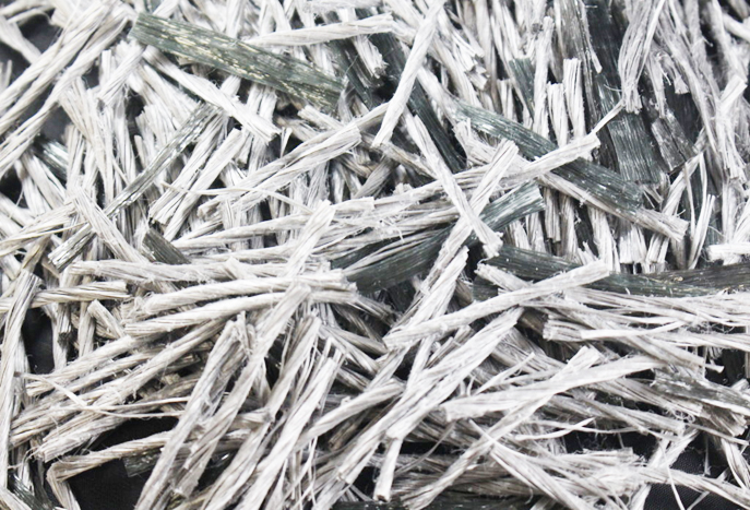
Lathe Waste: Mild steel fibre from the lathe waste was used as the fibre material. Spiral shaped fibres were selected for the casting. The fibre length was kept as a constant parameter and the volume of fibre addition as a variant. The length and width of the fibre will affect the concrete property, so careful selection of material should be done. The length of the fibre was maintained at 80mm, as shown in Fig 1.
Water: Normal tap water was used for casting and curing. The water was free from salt content.
Fig.1: Mild Steel Fibre from Lathe Waste
Mix Design
A concrete mix design was done for M25 grade concrete and the Mix proportion is listed below in Table 1. The mix design was designed based on IS 10262, with a water-cement ratio of 0.5. Spiral shaped fibres are added at various percentages by weight of the concrete. Cubes, cylinders and beams of standard size are cast for the various percentages and kept curing for 7, 14 and 28 days.
Experimental Detail
The project’s main aim was to understand the change in the properties of lathe waste fibre reinforced concrete. By considering the fibre volume as a variant, parameter casting works for all the percentages were done. Concrete specimens of cubes, cylinders and beams were cast based on Indian standards.
Compression Test: Cubical specimen of size 100x100x100mm was cast for all the percentages, and they were tested in the universal testing machine at a loading rate of 140 kg/cm2. Concrete mixes for all percentage of fibre were prepared, and it was compacted inside the mould. The samples were demoulded after 24 hours and kept in the curing tank for 7, 14 and 28 days. The test specimen was stored in a place free from vibration and cured in fresh water, the water was renewed every 7th day, and the water was at a temperature of 27º ± 2º C. On the day of testing, the samples were taken out of the tank, and the surface moisture was wiped off before testing. The specimen was loaded in the universal testing machine, and the compressive strength was found using the formula
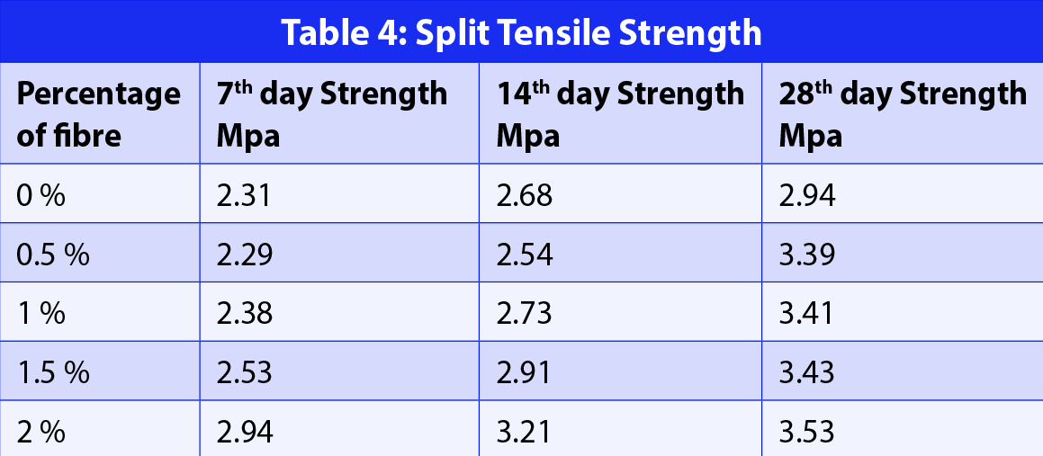
Split Tensile Strength: Standard size cylinders of diameter 100mm and height 150mm were cast for all percentage of fibre and kept under curing for 7, 14 and 28 days. On the day of testing, the samples were taken out of the tank, and the surface moisture was wiped off. The cylindrical specimens were loaded in the universal testing machine at 140kg/cm2 per minute. The failure load was determined and the specimen’s split tensile strength was determined by using the formula.
Flexural Strength Test: Prismatic samples of size 10x10x50cm were cast for all the mixes and tested using a digital flexural testing machine with a loading rate of 180 kg/cm2/min after a curing period of 7,14 and 28 days. A similar method of casting and curing was adopted as done for compression testing. After the required curing, the samples were loaded in the digital flexural testing machine, and the flexure strength of the sample was displayed in the testing machine. The formula used for calculating the strength is
Where P is the load at failure and l is the length.
Modulus Of Elasticity
Cylindrical specimens of size 150mm diameter and 300mm height were cast to determine the modulus of elasticity, and the specimens were kept curing for 28 days. On the day of testing, the samples were taken out from the curing tank, and the surface moisture was wiped off. The strain measuring cage was attached to the cylindrical specimen after leaving a space of 50mm from bottom and 50mm from the top of the specimen. The specimen was loaded into the universal testing machine. From the test results, the load-deflection pattern and stress-strain behaviour of concrete can be studied. Load up to 200kN was considered for the study. A deflection dial gauge was attached to study the load-deflection pattern. Based on the load-deflection pattern stress-strain, values were determined. From the stress-strain curve, the change in the modulus of elasticity with the fibre content was determined by the formula
Water Absorption: For checking the concrete’s water absorption, concrete cubes of size 100x100x100mm were cast and cured for 28 days. After 28 days of curing the samples, air-dried and then placed inside the oven at 110°C for 24 hours. After 24 hours, the samples were weighed and recorded as dry weight. The samples were then kept submerged underwater for 24 hours, and they were weighed again and recorded as wet weight. Water absorption was expressed in percentage:
Sorptivity Test: The Sorptivity test was done to study the rate of water absorption of the concrete. For that concrete cylinder of diameter 100mm and height 150mm were cast, and it was cured for 28 days. After 28 days of curing, the cylinder was cut into a smaller size of the height of 50mm. The inner part of the cylinder was selected for the study, and the samples were kept inside the oven at 110°C for 24 hours. Using insulation tape, the top and sides of the cylinder were covered, and the bottom part was left open. After the sample preparation, the sample was immersed in water with 5mm height from the bottom. Weights of the samples were measured at 30, 45 and 60 minutes. This test measured the rate of water absorption through the capillary rise.
Where,
W1 – Dry weight of the sample in kg
W2 – Wet weight of the sample in kg
A – Surface area of the cylinder which is exposed to water
δ – Density of water in kg/m³
T – Square root of time during the measurement in minutes
Non- Destructive Test: Non -Destructive Test (NDT) consists of a wide range of testing to assess the quality of the concrete without causing any damage to the specimen. In this research, an ultra-sonic pulse velocity test and rebound hammer test was conducted.
Ultra-Sonic Pulse Velocity Method: The basic principle of ultra-sonic pulse velocity is to determine the time taken by an electronic wave to passing through the concrete specimen. Based on the received waves, the quality of the concrete was analysed. Electroacoustic transducers produce an ultrasonic pulse, and by transmitting this pulse through the concrete specimen, the quality of the concrete was studied. By a receiving transducer, the fastest waves was detected, and their velocity was measured. Pulse velocity only depends on the elastic property of the concrete, so it is the better method to understand the quality of the material. In this test, after selecting the line of propagation of the wave, the transducer which propagates the wave was placed in one end and the receiving transducer at the other end. As the wave passes the velocity of the wave was displayed in the UPV machine. Based on this value, the quality was determined. For the testing concert cubes of size 100x100x100mm of age 28 days was used.
Rebound Hammer Test: Hardness of the concrete was measured by the rebound hammer test. Based on the rebound hammer number obtained from the test the hardness of the concrete was determined. The test was conducted by the procedure based on IS 13311 (Part 2): 1992. Rebound hammer consists of a tubular housing having spring controlled mass that slides over the plunger within it. During the testing, the plunger was pressed against the test specimen and the spring controlled mass rebounds. The range of the rebound varies with the surface of the specimen. The rebound value number was then compared with the standard values. For testing, concrete cubes of size 100x100x100 were used and rebound hammer number of a surface were taken three times in different points and the average value was compared with the standard values.
Results And Discussion Workability
The slump height of all the percentage concrete was calculated, and from the test results, it was observed that slump height was decreasing with an increasing percentage of fibre. The slump value is shown in Table 2. The addition of the fibre leads to an increase in the confining pressure between the fibre and the concrete mix, which causes a decrease in the value. The fibre will form a bond between the materials and arrest the falling of the concrete. Some other researches suggest the use of superplasticizers to overcome the decrease in workability. But for this study, no plasticizers were used since there was only a slight decrease in the value of slump height, and the resultant mix was sufficient.
Compression Test
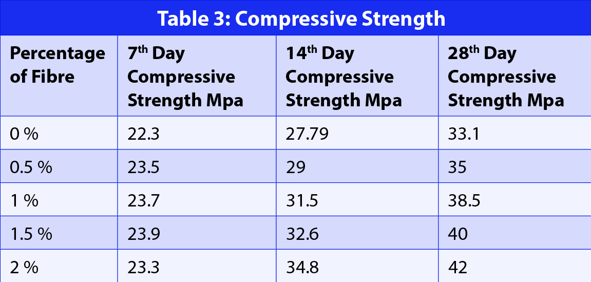
From the compressive test results, it was observed that the fibre addition in the concrete would support the compressive strength properties of concrete. The fibre added in the concrete has helped to prolong the failure of concrete, and as a result, the value obtained for fibre reinforced concrete under compression was greater than conventional concrete. It was observed that the value of compressive strength was increasing with an increase in fibre content, and the maximum value was obtained at 2% of fibre addition. It was also observed that the fibre added concrete shows a different crack pattern in the concrete cube. The values of the compressive strength of the cube are shown in Table 3.
From Table 3, it was observed that there was only a slight increase in strength on the 7th day compressive test, and after that, during the 14th day and 28th day, there was a remarkable improvement in the strength. The result shows a gradual increase in the strength of the 14th and 28th days.
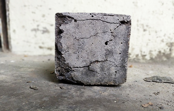
Fig. 2 shows the crack pattern in the cube after compression. The cube was not completely collapsed even after the failure, and the fibre added in concrete shows good resistance in the propagation of the crack. The failure pattern shows a small amount of collapse compared to conventional concrete.
Fig. 2: Cube after Compressive Test
Split Tensile Strength
Fibre-reinforced concrete is mainly adopted for improving the ductile behaviour of the concrete. From the test results, it was observed that the ductile properties of the concrete had been improved with an increase in fibre content [1-4]. The added fibre also takes part in load distribution in the specimen. Due to its ductile behaviour, the fibre can withstand load before its failure, and from the experimental results, the quantity of the fibre increases the load-carrying capacity of the concrete. Maximum tensile strength was obtained at 2% of fibre addition. Test results for all percentages of fibre addition at 7, 14 and 28 days are shown in Table 4.
Based on all the literature review and experimental data, the results show good agreement with the crack pattern and increased strength. Crack width of the cylinder was observed to be decreasing with the increase in the fibre content.
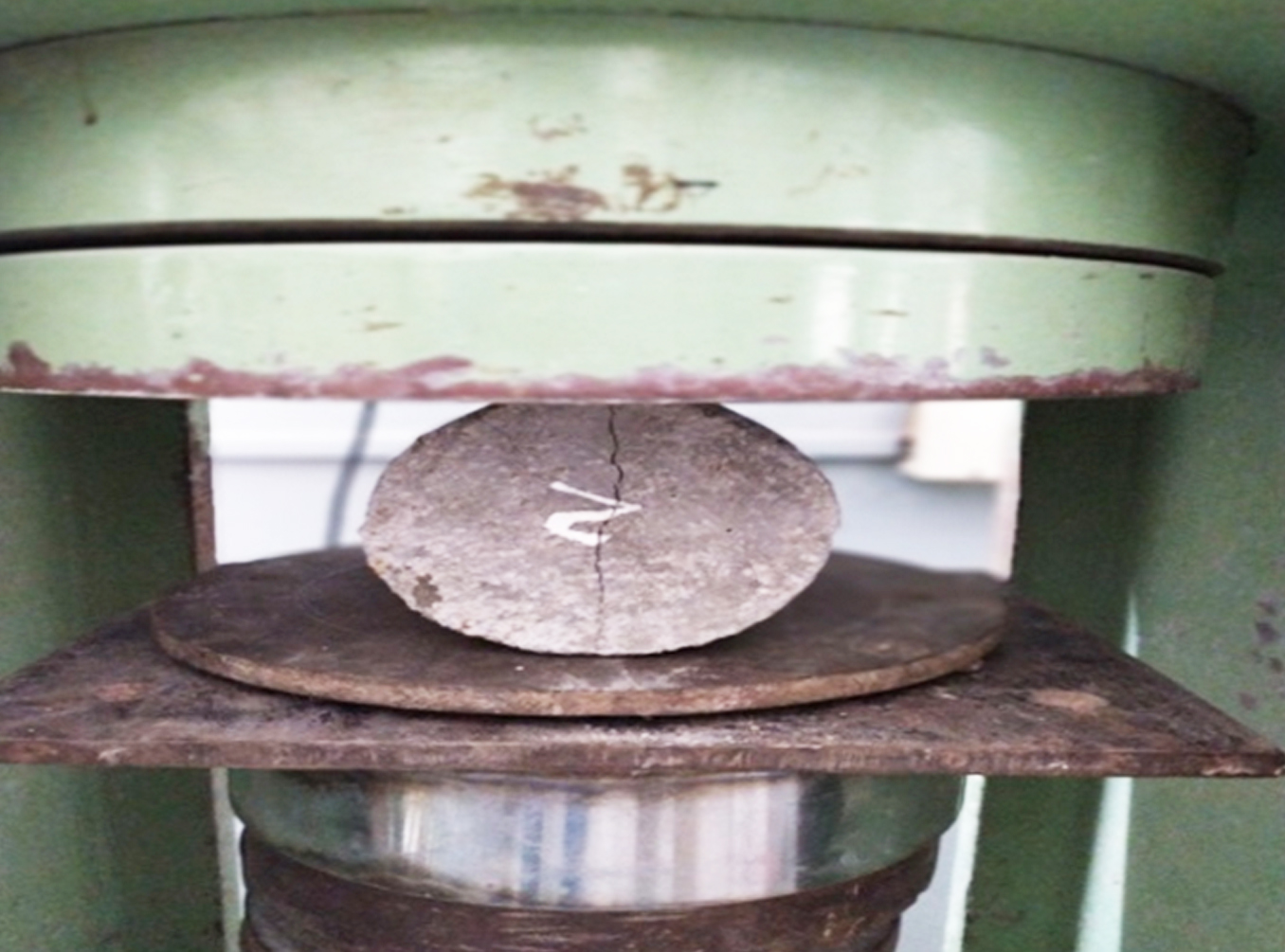
Fig. 3 shows the cylinder at failure. Only a slight crack is formed on the cylinder and it is also observed that the width of the crack decrease with increase in fibre content. For the case of conventional concrete, the cylindrical specimen was split into two pieces and for lathe waste reinforced concrete, the failure load of the cylinder was prolonged by the fibre.
Fig. 3: Cylinder under Split Tensile Strength
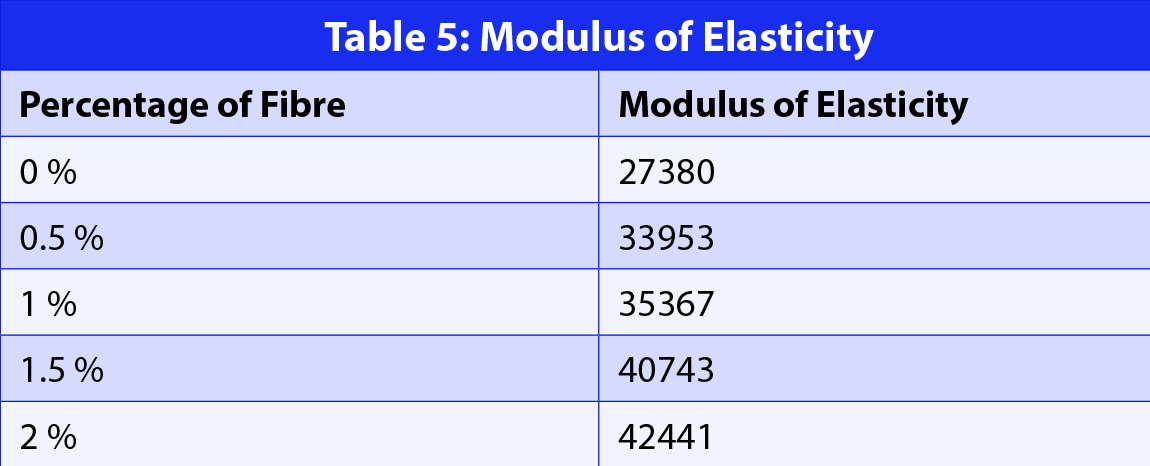
Modulus Of Elasticity
Based on the stress – strain values, the value of the modulus of the elasticity was determined. From the test data, it was observed that the value of the modulus of the elasticity was increasing with an increase in the fibre content. As per Indian code IS 456: 2000, Modulus of elasticity (Ec) is calculated by the 5000, where fck is 28th day compressive strength of the concrete. Therefore, as per IS code, the value for modulus of elasticity for conventional concrete should be 25000 kN/mm2. From the experiment, the value obtained for conventional concrete was 25,464 kN/mm2, which shows the adaptability of the test results. The values of modulus of the elasticity are exhibited in Table 5.
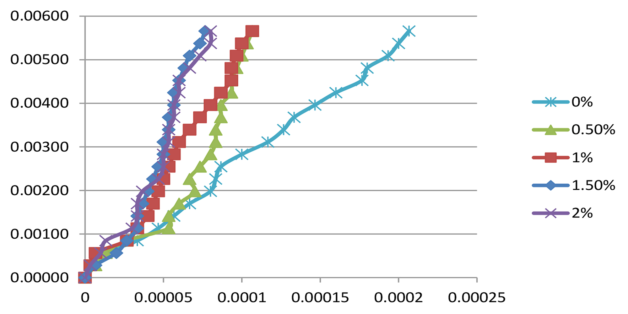
From Fig. 4, it is evident that the strain value of the concrete specimen was decreasing with the increase in the fibre content. From various literature reviews and the experiment conducted, we can say that the fibre resists the deformation of the concrete under loading and prolong the stress value. Therefore, the concrete can yield heavy loading with low deformation, and due to a decrease in the strain value, the value of modulus of elasticity will increase.
Fig. 4: Stress-Strain Behaviour
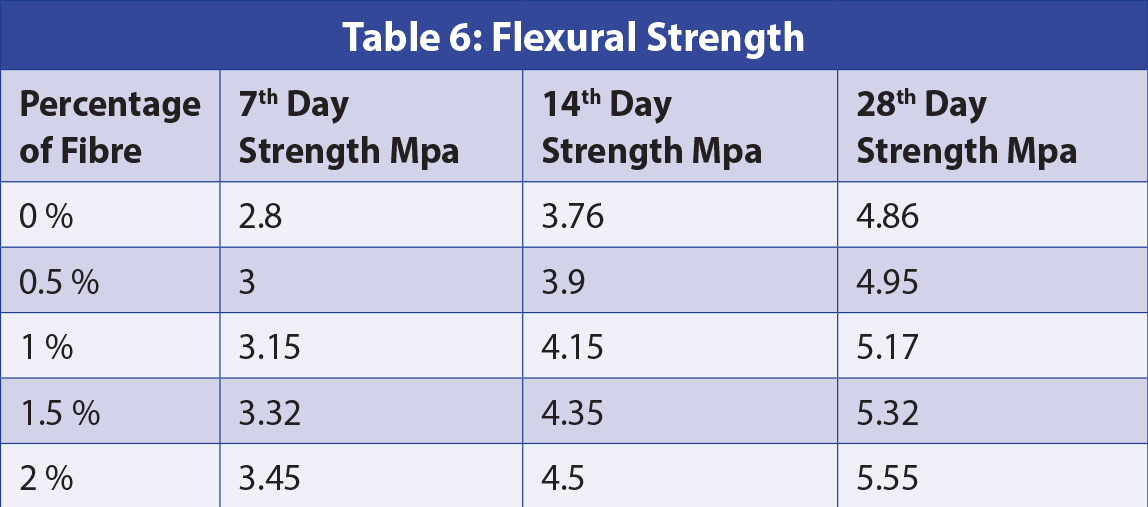
Flexural Strength
Fibre-reinforced concrete was mainly adopted to improve the ductile and bending behaviour of the concrete. From the test results, it was observed that the addition of mild steel fibre in concrete shows a progressive behaviour in the bending behaviour of concrete. Improvement in the flexural strength of the concrete with an increase in the amount of mild steel fibre was observed. Mild steel fibre added in concrete will take part in load distribution in the concrete beam
and the fibre will support yielding under loading. During testing, all the concrete beam has undergone brittle, but for fibre reinforced concrete, the failure load was increasing with an increasing percentage of mild steel fibre. The value of the flexural test of fibre reinforced concrete is shown in Table 6 below.
From the results, it is evident that an increase in the amount of steel fibre has a positive impact on flexural behaviour. The change in strength is observed from the 7th day onwards.
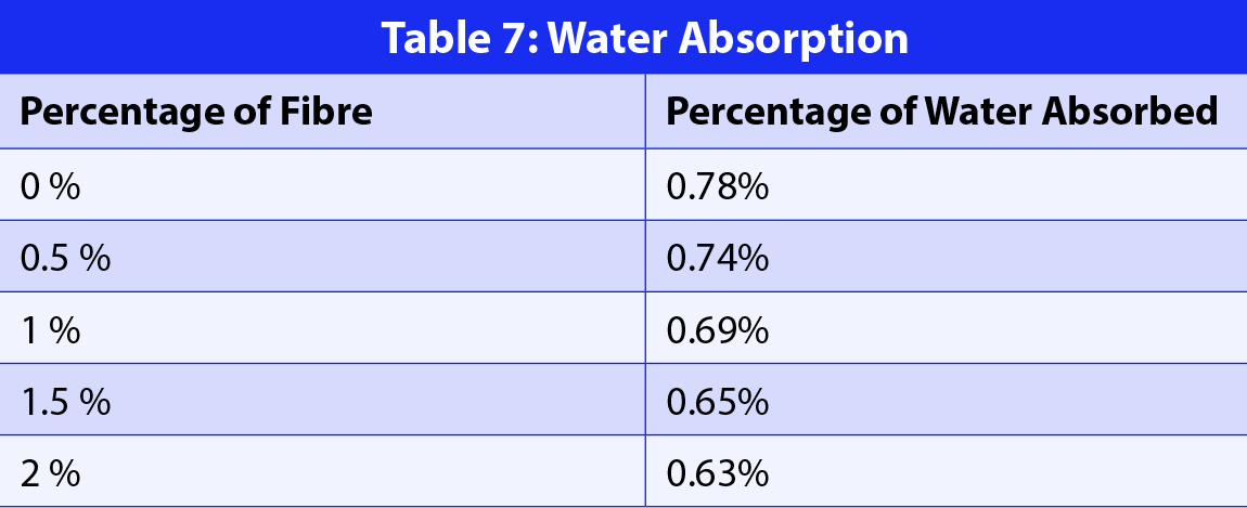
Water Absorption
The water absorption test was conducted under the study of the durability of concrete. The amount of water undergone absorption depends on the porosity of the concrete specimen. Thereby, an idea regarding the porosity in the concrete can be made. The addition of mild steel fibre helps to reduce the porosity in concrete by filling the voids and by providing strong bonding in concrete. From the test results, it was observed that the amount of water absorption was reduced with the increase in the amount of fibre. Table 7 shows the results, which reflect the decrease in the percentage of water absorption.
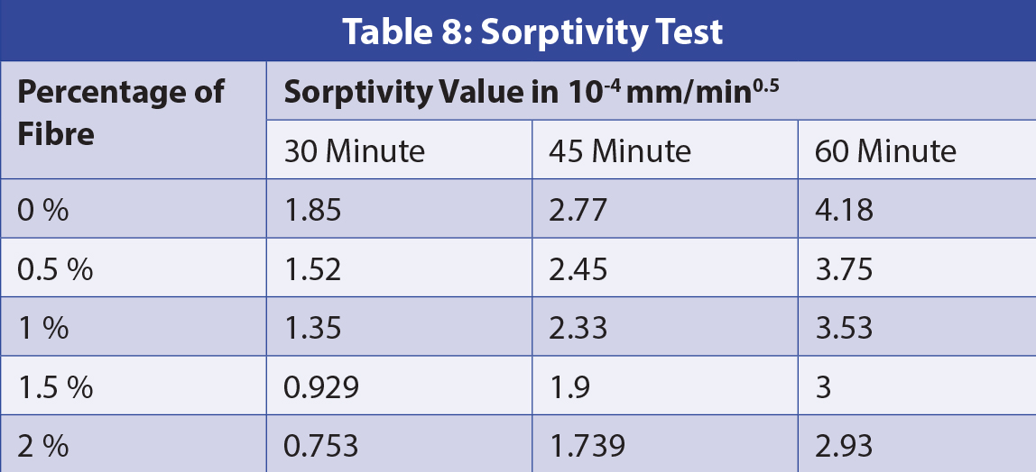
Sorptivity Test
It was observed that the rate of water absorption was decreased with an increase in fibre content. The value shows good agreement with the water absorption value because the value of water absorption was also decreasing with an increase in fibre content. The results from the sorptivity test are shown in Table 8.
It was observed that the rate of water absorption was increasing with time, but it was decreasing with increase in fibre content.
The maximum rate of absorption was obtained for conventional concrete (4.18X104 mm/min0.5 at 60 Min), and the minimum value was obtained for concrete with 2% fibre (2.93X104 mm/min0.5 at 60 Min).
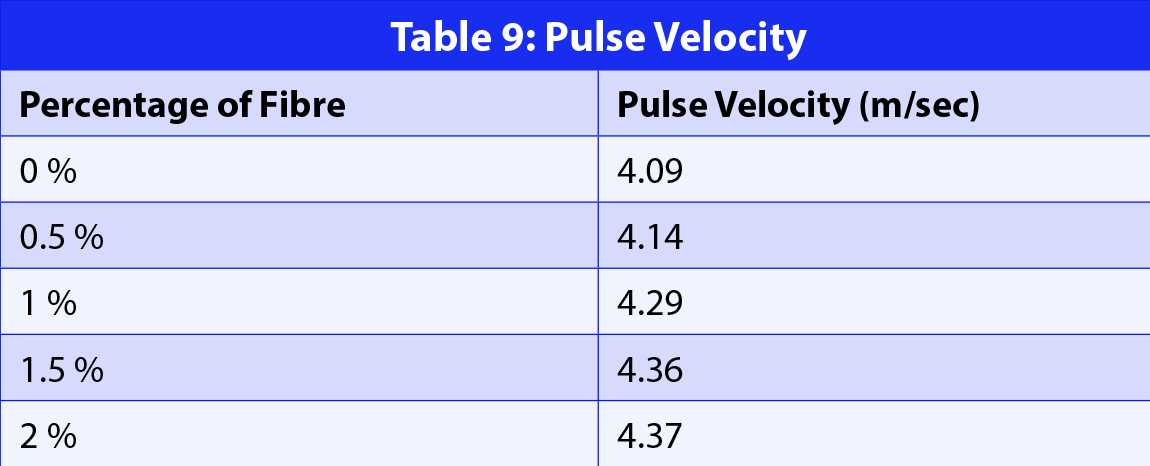
Ultra-Sonic Pulse Velocity (UPV)
The UPV test was conducted, and the average values are recorded in Table 9. As per Indian standards, the values greater than 4 km/sec come under excellent quality concrete.
Both lathe waste reinforced concrete and conventional concrete come under good quality concrete, and the value of UPV was observed to be increasing with an increase in fibre content
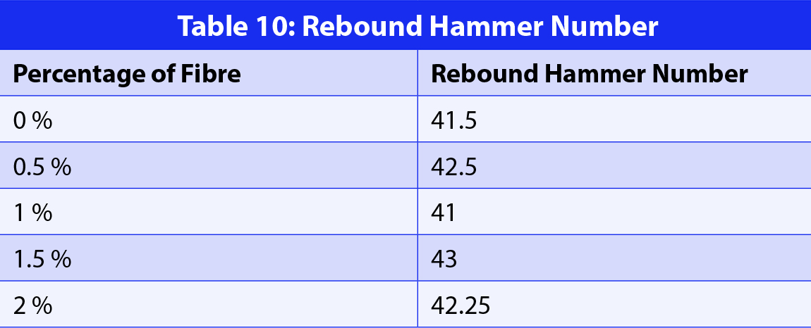
Rebound Hammer Test
As per Indian standards, for very good and hard layer concrete, the value of the rebound hammer number should be greater than 40. Here, all the specimen have a value greater than 40, so all specimen comes are of good quality. The average value of all the specimens is shown in Table 10.
Conclusion
From the experimental study, the results indicate that:
From the slump test, it was observed that the addition the mild steel fibre increases the confining behaviour between the fibre and concrete materials, leading to a decrease in the value of slump height. For 2% fibre addition, the value of slump height was dropped to 54mm from 64mm at 0% addition.
The value of compressive strength was observed to be increasing with the increase in fibre content. For 2% fibre addition, the value of compressive strength obtained was 42 MPa, whereas, for conventional concrete, the compressive strength was 33.1MPa.
Remarkable improvement in the split tensile strength was observed in the fibre reinforced concrete. Due to the internal bonding provided by the fibre, the width of the failure crack was decreasing with an increase in the fibre content. The maximum value was obtained at 2% of fibre addition was 3.53 MPa.
Flexural strength was also improved with an increase in fibre content. The addition of the fibre resists the propagation of the crack and prolongs the failure load of the beam. The maximum value was obtained at 2% was 5.55 MPa.
The effect on modulus of elasticity of concrete was also observed to be increasing with the increase in the fibre content. From the test, it was observed that the fibre reinforced concrete could resist more stress with less strain value. At 2% fibre addition, the value obtained for modulus of elasticity was 42,441 MPa, and for convention concrete, the value was 25,464 MPa.
Due to the internal bonding provided by the fibre, the pore space inside the concrete was reduced. Therefore, from the test results, the value of water absorption was decreasing with the increase in fibre content. The rate of absorption measured from the sorptivity test shows a good correlation with this.
The sorptivity test results show that the rate of absorption was decreasing with the increase in fibre content.
From the NDT test, it was observed that the casted specimen was of good quality.
Qian Chunxiang and Indubhushan Patnaikuni. “Properties of high-strength steel fibre-reinforced concrete beams in bending”.Cement and Concrete Composites 21 (1999) 73-81.
Seetharam. P. G, Vidhya. S, Bhuvaneswari. C, Vishnu Priya. M (2017). Studies on Properties of Concrete Replacing Lathe Scrap. International Journal of Engineering Research & Technology (IJERT) , 6(3), 20-28.
Poorva Haldkar, Ashwini Salunke (2015) .Analysis of Effect of Addition of Lathe Scrap on the Mechanical Properties of Concrete”. International Journal of Science and Research (IJSR)
Pooja Shrivastava, Dr. Joshi Y.P. (2015) .Reuse of Lathe Waste Steel Scrap in Concrete Pavements. International Journal of Engineering Research and Applications, 4(12), Part 4.
Prof. Kumaran M, Nithi M., Reshma K. R. (2015). Effect of lathe waste in concrete as reinforcement international journal of research in advent technology.
Abbas Hadi Abbas(2011). Management of steel solid waste generated from lathes as fibre reinforced concrete. European journal of scientific research 50 (4).
Fangyuan Li , Yunxuan Cui, Chengyuan Cao and Peifeng Wu. “Experimental study of the tensile and flexural mechanical properties of directionally distributed steel fibre-reinforced concrete”. Materials: Design and Applications 0(0)
Wafa, F. F., and Ashour, S. A. 1992. “Mechanical properties of high strength fibre reinforced concrete.” ACI Mater. J., 895, 449–455
Nataraja, M. C., Dhang, N., and Gupta, A. P. 1999. “Stress strain curve for steel-fibre reinforced concrete under compression.” Cem. Concr. Compos, 21, 383–390.
Mander, J. B., Priestley, M. J. N., and Park, R. 1988b. “Theoretical stress-strain model for confined concrete.” J. Struct. Eng., 1148, 1804–1826.
Jo, B. W., Shon, Y. H., and Kim, Y. J. 2001. “The evaluation of elastic modulus for steel fibre reinforced concrete.” Russian J. Nondestructive Testing, 372, 152–161.
Dwarakanath, H. V., and Nagaraj, T. S. 1991. “Comparative study of predictions of flexural strength of steel fibre concrete.” ACI Struct. J., 886, 714–720.
Zhao, M.; Zhao, M.; Chen, M.; Li, J.; Law, D. An Experimental Study on Strength and Toughness of Steel Fibre Reinforced Expanded-Shale Lightweight Concrete. Constr. Build. Mater. 2018, 183, 493–501.