Dr. S.C. Maiti
Former Joint Director
National Council for Cement and Building Materials
Concrete mix proportions are selected for the desired workability and the target 28-day compressive strength of concrete. The mix proportions should be economical and at the same time, the concrete should satisfy the durability requirements, for the exposure condition, at which the structures shall provide the service. The Indian Standard Code of practice for plain and reinforced concrete provides the minimum cement content and maximum water-cement ratio in concrete, for different exposure conditions. The Code also recommends at least 25% fly ash or at least 50% Ground Granulated Blast furnace Slag (GGBS) as part replacement of low alkali ordinary Portland cement, to combat the deleterious alkali-silica reaction (if any), in concrete. In mass concrete foundation structures, (OPC + fly ash) or (OPC + GGBS) is required to be used in concrete, to avoid any temperature- related ill effects in concrete.
With the above-mentioned considerations, Indian Standard Guidelines are followed to select the concrete mix proportions and the quantities of cement, water, aggregates, admixture etc. per cubic metre of concrete are calculated. In this paper, details on different relationships as given in the guidelines, between water-cement ratio/water-cementitious materials ratio and 28-day compressive strength/flexural strength of concrete, those between workability of concrete and mixing water content, absolute volumes of coarse and fine aggregates for different Maximum Size of Aggregate (MSA), and finally their quantities per cubic metre of concrete, as required for different types of concrete have been covered. The types of concrete considered are: medium and high strength concrete, self-compacting concrete, mass concrete, roller-compacted concrete, fiber-reinforced concrete and pavement concrete.
Concrete Mix Proportions For Medium Strength And For High Strength Concrete
For estimating the target 28-day compressive strength of concrete, IS 102621 provides standard deviation values to be assumed, when sufficient test results are not available for a particular grade of concrete. As soon as 30 test results are available, actual standard deviation values shall be used for the mix proportions. The suggested standard deviation values are shown in Table 1.
Note 1: The above values correspond to the site control having proper storage of cement, weigh batching of all materials, controlled addition of water, regular checking of all materials, aggregate gradings and moisture content and regular checking of workability and strength. Where there is deviation from the above, the values given in the above table shall be increased by 1N/mm2.
Note 2: For grades M65 and above, the standard deviation may be established by actual trial, before finalizing the concrete mix.
The water-cement (w/c) ratio for the target 28 day strength is selected from an established relationship between the two. In the absence of such data, Figure 1 may be followed to start with.
Curves 1, 2 and 3 of Fig. 1 are for 28 day compressive strength of cement (33-grade, 43-grade and 53-grade level). While using Portland Pozzolana Cement (PPC) and Portland Slag Cement (PSC), the appropriate curve as per actual strength may be used. In the absence of test results of ppc and psc, curve 2 may be used to start with.
Fig.1: Relationship Between Water-Cement Ratio and 28-Day Compressive Strength of Concrete
For high strength concrete of M65 to M80, IS 10262 provides the following relationship, as given in Table 2.
Note: The W/Cem. ratios in Table 2 are for 28-day cement – strength of 53 MPa and above. For cement of other strengths, suitable adjustment may be made by reducing W/Cem. ratio. The mixing water contents of concrete for a slump of 50mm as given in IS10262 are shown in Table 3.
The entrapped air contents of concrete are also slightly different in the two types of concrete (Table 4). In high strength concrete mixes, the entrapped air content is expected to be less.
Note: It is suggested that the above values are approximate and the actual air content of concrete may be measured at the sites of construction and used in the mix design calculations.
Once the W/c ratio and mixing water content decided, the cement content of concrete is calculated. If mineral admixture e.g. fly ash, Ground Granulated Blast furnace Slag (GGBS) or silica fume is used, their percentage by weight of total cementitious materials can be based on project requirement. For example, minimum 25% fly ash or minimum 50% GGBS for hydro-electric project is required to combat the deleterious alkali-silica reaction in concrete. Silica fume, 5-10% can be used for abrasion resistance and to increase the strength of concrete. The silica fume is used as part replacement of cement and its proportion is 5-10% of the cement content of the mix, as per IS 4562.
When fly ash is 20% or more and GGBS is 30% or more, to get the equal 28-day strength of concrete, the total cementitious material content is to be increased by 10%. Generally GGBS content is much higher these days, may be more than 50%. In coastal environment for concrete piles, 70% GGBS is required because of aggressive environment. In such case the increase in total cementitious materials content may have to be increased by more than 10%. This can be fixed based on experience and trials.
The cementitious material content so calculated and the w/c ratio or w/Cem ratio decided, shall be checked against the durability requirement as per IS 456, as shown in Table 5.
Note: The cement contents are irrespective of the grade and type of cement and is inclusive of additions i.e. mineral admixtures.
Adjustments
The following adjustments may be made to the minimum cement content for aggregates other than 20mm MSA.
The chemical admixture content may also be fixed by trials, to satisfy the workability requirement of concrete. The admixture must be compatible with the cement. If not, there will be segregation and bleeding of concrete. Next, the absolute volumes of these materials i.e. of cement, fly ash/GGBS/ silica fume, water and chemical admixture are calculated using their specific gravity values. The entrapped air content is % of volume of concrete as per Table 4. The remaining volume in a cubic metre of concrete is of (coarse aggregate + fine aggregate).
The absolute volume of coarse aggregate is decided based on MSA, and grading of fine aggregates (Table 6). These values are for the W/c or W/cem ratio of 0.50. For other values as decided based on target strength, the volumes need to be adjusted. The adjustments are as follows.
For every 0.05 decrease in w/c ratio or w/cem. ratio, the volume of coarse aggregate is to be increased by 0.01m3 and vice versa.
Notes:
Volumes of aggregates are based on aggregates in saturated surface dry condition.
Volumes are based on crushed rock angular aggregate.
Suitable adjustments are required for aggregates of other shapes e.g. rounded or sub-angular aggregates.
IS 3833 states that, fine aggregate conforming to grading zone IV shall not be used in reinforced concrete, unless tests have been made to ascertain the suitability of the proposed mix proportions.
Crushed stone fine aggregate or mixed sand (natural sand + crushed stone) may need lesser fine aggregate content and therefore in that case, volume of coarse aggregate shall be suitably increased.
The fine aggregate for medium strength concrete is generally in the range of 28-40% for different MSA and are based on the grading of fine aggregate. Typically, for 20mm MSA, zone II grading, the fine aggregate content is 33%. For 40mm MSA, it is 28% and for 10mm MSA, it is 40%. IS456 states, ‘the proportion of fine aggregate should be adjusted from upper limit to lower limit progressively, as the grading of fine aggregate becomes finer and the maximum size of coarse aggregate becomes larger. Graded coarse aggregates shall be used.’ For coarse fine aggregate of zone I grading, the quantity of fine aggregate is to be increased by about 1.5%, and for finer grading, say zone III grading, the quantity of fine aggregate is to be reduced by about 1.5%, and for zone IV grading, the quantity of fine aggregate is to be reduced by about 3%. For rounded coarse aggregate, the quantity of fine aggregate is to be reduced by about 7%. For high workability concrete or pumpable concrete, however, the quantity of fine aggregate shall be 40% and higher, irrespective of the grading of fine aggregate. IS 383 permits crushed stone fine aggregate and mixed sand i.e. blend of natural sand and crushed stone fine aggregate to be used in concrete. With the above considerations and using table 6, the absolute volumes of coarse aggregate and fine aggregate are decided, and their quantities per cubic metre of concrete are calculated, using their specific gravity values, and trial mixes can be conducted.
Trial Mixes
The concrete mix proportions thus fixed for a cubic metre of concrete, are for Saturated Surface Dry (SSD) aggregates. (i) For dry aggregates, the quantity of mixing water shall be increased by the amount required for their absorption. Coarse aggregate may absorb about 0.5% water, and fine aggregate may absorb about 1% water. (ii) In case of wet aggregates, the quantity of mixing water is to be reduced by the amount of extra water available in coarse and fine aggregates, other than their absorption. In both the cases i.e. (i) and (ii), the quantity of aggregates (both coarse and fine aggregates) are to be adjusted properly.
For the first trial mix of 0.05m3 concrete, the workability shall be measured. There should not be any segregation or bleeding. That may be because of incompatibility of super plasticizer with the cement. Sometimes, concrete mix may not be cohesive and may need higher fine aggregate content. If the workability is not achieved, the mix needs to be adjusted with more water or more chemical admixture. With the modifications in the mix, the mix proportions shall be recalculated, keeping w/c ratio or w/cem ratio at the preselected value, to obtain the desired 28-day compressive strength of concrete. This will comprise Trial mix no. 1. Two more mix proportions with + 10% of the w/c ratio or w/cem. ratio shall be worked out, and the three concrete mixes are to be made simultaneously, one after another, and workability measured. If the desired workability is achieved, concrete cubes can be cast for 7-day and 28-day compressive strength concrete. With the lower w/c ratio or lower w/cem ratio, if the workability of concrete is less, the chemical admixture content may have to be increased marginally. with the test results of 28-day compressive strength of concrete of the three trial mixes, a relationship between w/c ratio or w/cem ratio and 28-day compressive strength of concrete can be plotted and the right w/c ratio or w/cem. ratio can be estimated for the target 28-day compressive strength of concrete. The finalized concrete mix proportions can be recommended for field trials.
For obtaining the recommendation on concrete mix proportions early, the accelerated strength testing can be carried out by ‘boiling water method’ as per IS 90134. In this method, 3 cubes from each trial mix i.e. total 9 cubes (along with their moulds) are to be normally cured in the laboratory for 23 hours under wet gunny bags and with cover plates fixed on them, to be placed in boiling water in a steel tank for 3½ hours. Next the cubes are removed from boiling water, cooled for 2 hours in the laboratory, and then de-moulded and tested for compressive strength. From the average accelerated strength of the three concrete mixes, the approximate 28-day compressive strength of concrete can be estimated from a relationship established beforehand. A typical correlation is shown in Fig. 2.
Fig. 2
Self-Compacting Concrete
The Self-Compacting Concrete (SCC) will have high workability, the workability measured by ‘slump flow test’, the slump flow5 being in the range of 550-850mm. the Maximum Size of Aggregate (MSA) can be 20mm. A smoother aggregate is preferred e.g. gravel aggregate or crushed gravel aggregate. The fine aggregate content will be higher in the range of 48-60%. The super plasticizer (polycarboxylate ether based) and a Viscosity Modifying Admixture (VMA) have to be used. The powder content (<0.25 mm size) of the mix will be in the range of 400-600 Kg/m3 of concrete. The water content is generally higher, 150-210kg/m3 of concrete. Fly ash content specified is 25-50% and GGBS content specified is 50-70%. The water-powder ratio will be 0.85 to 1.10 by volume. Typically for a M30 grade concrete for a high workability of 760-850mm slump flow, quantity of materials per cubic meter of concrete1 are : opc (43 grade) = 287kg, fly ash=155kg(35%), water = 190kg, super plasticizer = 0.6%, VMA=0.2%, water- powder ratio (by volume) = 0.99.
For low volume rural roads, IRC:SP:626 provides guidelines on self- compacting concrete, and suggests typical range of S.C.C. mix composition for M30 to M40 grades of concrete (Table 7). For village roads, the Guidelines suggests slump flow of 400mm and V-Funnel flow time5 of maximum 8 seconds.
Mass Concrete
Mass concrete generally refers to massive structures, e.g. foundations of bridge piers or high-rise building columns or concrete dams. In mass concrete, temperature of concrete due to heat of hydration of cement has to be lower. If the temperature difference within the mass of concrete is more than 200C, cracks may develop in concrete.
It is essential therefore to use 33-grade opc or Portland Pozzolana Cement or Portland Slag Cement, or (opc + fly ash) or (opc + GGBS) in mass concrete. Generally, lower grade of concrete is used in mass concrete. In foundation structures, grades of concrete are: M20 to M40. In concrete dams, the concrete grade is generally M10. Quantity of mineral admixtures are not fixed, but generally fly ash content can be about 20-30% and GGBS content can be about 50%. For resisting the deleterious alkali-silica reaction in hydro-electric project structures, the minimum fly ash content specified is 25% and minimum GGBS specified is 50%. In foundation structures, 40mm MSA should be used, and in concrete dams, the MSA can be 75mm/80mm or 150mm. IS 10262 provides the mix design procedure, considering mixing water content for different MSA, water-cement ratio Vs 28-day compressive strength of concrete (Fig.1) and air content similar to those of normal mix design procedure.
But the target 28-day compressive strength calculated shall be increased by 20% for concrete with 75/80 mm MSA, and 25% for concrete with 150mm MSA. This is to account for higher strength achieved after wet-screening the fresh concrete through 40mm sieve, for casting 150mm size cubes. This increase in strength is because, after wet screening of concrete, the mix becomes richer in cement content. A special requirement of mortar content of mass concrete has been specified (Table 8) based on American practice.
Roller – Compacted Concrete
The mix proportioning method for zero-slump roller- compacted concrete differs from the conventional concrete in that the moisture content of the concrete should be dry enough to support the weight of the vibratory roller and yet a cohesive concrete mix. Instead of fixing the water-cement ratio, the water content of the mix is fixed in the range of 4-7% by weight of total dry material. The optimum moisture content which gives maximum density shall be determined. For pavement concrete, the MSA is 16.5mm, whereas for concrete dams, the MSA can be 50 or 75mm. IRC: SP: 687 suggests fly ash content up to 35% and GGBS content up to 50%. In roller- compacted concrete dams, the fly ash content of 65% has been used. For pavement, the characteristic strength is 35 MPa for State and National Highways, whereas for rural road, it is 30 MPa. The corresponding flexural strength shall be 4 MPa and 3.8 MPa respectively.
Since, roller-compacted concrete dams are of low grade concrete, say M10, the cement content of concrete is considerably lower, than that of pavement concrete of M30 or M35. With 75mm MSA, Willow Creek dam concrete contained cementitious material of 66.5 kg/m3. The mixture containing 47.5 kg/m3 of cement plus 19.0kg/m3 of fly ash, developed compressive strength of 18.2 MPa at 1 year. Generally, roller- compacted concrete dams containing cementitious material content between 104 and 178 kg/m3 produced an average compressive strength of 13.8 to 20.7 MPa at the age of 90 days to 1 year8.
Fiber Reinforced Concrete
The Fiber-Reinforced Concrete (FRC) is generally used for impact and abrasion resistance, especially for concrete pavement or for factory floors or in defence applications, where blast resistance is required for buildings, defence installations, air field pavements and bridges. Steel or polypropylene fibers can be used. For pavements with steel or polymeric fibers, usually fiber reinforced concrete having characteristic of flexural strengths of 5 to 8MPa may be used. The maximum size of aggregate is generally of 20mm. The fiber dose is percentage by volume of concrete. The polypropylene fiber of 32 µm size at about 1.5 kg/m3 of concrete can be used in high strength concrete. The steel fiber 0.5 to 1.0% by volume of concrete (about 40-80kg/m3), crimped, hooked ends or trough shaped, dia. 0.5-1.0mm, and aspect ratio 50-100. The polypropylene fibers 0.50 to 2.0% by volume of concrete (about 4.5-18 kg/m3 of concrete), can be used. The specific gravity of steel is taken as 7.85 and that of polypropylene is taken as 0.91. Normally fibers of 20mm length give good performance. Fiber-reinforced concrete controls shrinkage-cracking, and is resistant to drying shrinkage. For resisting cracks in early hours (1 to 8 hours), polymeric micro fibers of 0.1 to 0.2% by volume i.e. about 0.90 kg/m3 to 1.8 kg/m3 of concrete has been used with success9. Fiber-reinforced concrete has been used to provide durable concrete pavements and bridge decks, with improved crack-resistance and reduced slab thickness.
In 1981-’82, R&D work was carried out on steel fiber reinforced concrete, on the development of different shapes of steel fibers, their aspect ratio, concrete mix design and applications in air field pavements10. Out of different shapes (straight, crimped, hooked and trough), trough shaped fibers were found to be most efficient in the development of flexural strength and toughness of concrete. On the mix design front, it was observed that, about 15% more volume of paste (i.e. cement + water) was required than that of conventional plain concrete. This is because, the fibers need more paste to coat them properly. The fine aggregate content is about 50%, and the aspect ratio of fibers of 80 gave maximum increase in the flexural strength of concrete. The conventional concrete mix with 40mm MSA was designed for 3.8MPa flexural strength. The mix had a cement content of 330 kg/m3, with a water-cement ratio of 0.48. For fiber-reinforced concrete, MSA of 20mm chosen, the cement content was 410 kg/m3 and a water-cement ratio of 0.65. ‘Trough’ shaped steel fibers of 106 kg/m3 (which is about 1.4% by volume of concrete), with dia. of 0.45mm was used. The concrete which developed a flexural strength of 7.0-8.0 N/mm2, was laid in the taxi tracks of the Indira Gandhi International airport, New Delhi. IRC: 1511 permits use of fiber- reinforced concrete to reduce shrinkage – cracking and to improve post-cracking residual strength of concrete pavements. For fibers and other details, the Code gives reference to IRC: SP: 469.
According to the guidelines of IRC: SP: 46, steel fibers should have an ultimate tensile strength of at least 800 MPa. Fibers can be straight or deformed. Fibers can be supplied loose or collated (i.e. glued with a water-soluble adhesive that dissolves during the mixing of concrete). Collated fibers have a lower tendency of balling. Sometimes, steel fibers are supplied with zinc coating. As a guide, for improved performance, steel fibers with hooked ends and having length of 50 to 60mm may be used. The polymeric fibers with low elastic modules are normally used to control plastic shrinkage cracking. Macro polymeric fibers of 30 to 60mm length of higher elastic modules, can increase the toughness and strength of FRC pavements. Macro fibers have diameter more than 0.2mm. Micro fibers are 12 to 40mm length and have diameter less than 0.2mm. Table 9 shows range of proportions of FRC for pavement applications, and the guidance is for an initial trial mix.
Pavement Concrete
Pavement concrete (for National and State highways) in generally of M40 grade. The corresponding flexural strength is 4.5 N/mm2. Rural low-volume roads are of M30 grade concrete. For National and State highways, the workability of concrete shall be 20 to 30mm slump, for concrete laid with slip form paver and 40 to 60mm for concrete laid with fixed-form paver11. For rural roads, a slump of 30 to 50mm has been suggested at the paving site for compaction by hand-operated machines6. The Guidelines for pavement with low-volume roads IRC: SP: 62 also suggests zero-slump roller compacted concrete, and high-workability self-compacting concrete, with super plasticizers and mineral admixtures e.g. fly ash, silica fume, rice husk ash, metakaoline and ground granulated blast furnace stag.
The pavement concrete shall contain both chemical admixtures and mineral admixtures. The maximum quantity of chemical admixture shall be 2% by weight of the cementitious materials (cement + fly ash/GGBS/silica fume). Fly ash up to 25% by weight of cementitious materials, and shall conform to IS 3812 (Part 1)12. The GGBS shall conform to IS: 671413 and up to 50% by weight of cementitious materials can be used with 43 grade or 53 grade OPC. The silica fume up to 10% by weight of OPC can be used, if specified in design for abrasion resistance. the Metakaoline of fineness of 700 to 900 m2/kg can be used up to 20%.
The MSA for pavement concrete shall be 31.5mm and the combined grading (of coarse aggregate + fine aggregate) for 31.5mm, 26.5mm and 19mm maximum sizes have been specified in IRC:1511, as well as in IRC:4414. IRC: 44 gives concrete mix design procedure based on 28-day compressive strength, as well as based on 28-day flexural strength. The suggested relationships (in the absence of an established relationship for the materials in hand) are shown in Table 10 and Table 11 respectively.
The approximate mixing water contents for different maximum sizes of aggregate are shown in Table 12.
The Volume of coarse aggregate per unit volume of total aggregate for different MSA and different grading zones of fine aggregate is shown in Table 13.
The quantities of different constituent materials per cubic metre of concrete are calculated by absolute volume method, considering the air content of concrete as shown in Table 14.
Concluding Remarks
The details on concrete mix proportions for different types of concrete have been highlighted. They are mostly based on Indian Standard recommended guidelines. The values of standard deviation suggested for high strength concrete of M65 and above are 6.0 N/mm2. This is on the higher side, as lower values are expected in practice, with better quality control in high-strength concrete. The entrapped air in concrete, as suggested in IS 10262 and IRC 44, for different MSA are also approximate. The values should be determined at the sites of construction, and actual values should be used in mix design calculations. The relationships (given in figure and tables) between water-cement ratio/ water-cementitious materials ratio Vs 28-day compressive strength/28-day flexural strength of concrete (for pavement concrete) are tentative and approximate. Therefore, if established relationships are available, they should be used for mix design.
For self-compacting concrete, the procedure of mix selection is based on European guidelines. The fly ash content (25-50%) and GGBS content (50-70%) as suggested in IS 10262 are on the higher side, and may not be correct. Such high mineral admixture content will reduce the strength of concrete. The mass concrete mix proportioning method suggested is based on American practice, where mortar content for different MSA and two types of aggregate (crushed rock and rounded gravel) have also been suggested. The zero-slump roller-compacted concrete mix proportioning method as suggested in IRC: SP: 68 for pavement concrete is much different. In this case, the water content is based on percentage of total dry material, including fly ash (up to 25%) or GGBS (up to 50%). But in roller-compacted concrete dams, the fly ash content of 50-65% is generally used.
The fiber reinforced concrete is basically for impact and abrasion resistance and for crack resistance. The fiber content is expressed as % by volume of concrete. The compressive strength of concrete increases marginally but the flexural strength increases by about 80-100% than that of plain concrete without fibers. The R&D work carried out at the Cement Research Institute of India in 1982 provides the details on the mix proportions of steel fiber reinforced concrete and its pavement –applications. But those days, super plasticizers were not available. So, concrete mix proportions suggested will undergo some changes, for fiber reinforced concrete with super plasticizers.
The pavement concrete mix proportions are marginally different from the mix proportions for structural concrete. This is mainly because in pavement, flexural strength is the main consideration. Different MSA (31.5mm, 26.5mm, 19.0mm and 9.5mm) are used in concrete pavements. The 33-grade opc and fine aggregate of grading zone IV are excluded. Although IRC 44 provides mix design procedures based on 28-day flexural strength and also based on 28-day compressive strength of concrete, it is always preferable to follow the 28-day compressive strength, to choose the mix proportions and then we can have correlation made between 28-day compressive strength and 28-day flexural strength on 30 specimens, on the materials in hand. This is because, the test method for flexural strength is not consistent, and can vary considerably.
References
IS 10262 Indian Standard Concrete Mix Proportioning – Guidelines. Bureau of Indian Standards, New Delhi, 2019.
IS-456 Indian Standard Code of Practice for plain and Reinforced Concrete, 2000 (with Amendments, 1,2,3,4 and 5). Bureau of Indian Standards, New Delhi.
IS 383 Indian Standard Specification for Corse and Fine aggregate for Concrete. Bureau of Indian Standards, New Delhi, 2016.
IS 9013 Indian Standard Method of Making, Curing and Determining Compressive Strength of Accelerated Cured Concrete Test specimens. Bureau of Indian Standards, New Delhi, 1978.
IS 1199 (Part 6) Fresh Concrete – Methods of Sampling, Testing and Analysis. Part-6: Tests on Fresh Self Compacting Concrete. Bureau of Indian Standards, New Delhi, 2018.
IRC: SP: 62 Guidelines for Design and Construction of Cement Concrete pavements for Low Volume Roads. Indian Roads Congress, New Delhi, 2014.
IRC: SP: 68 Guidelines for Construction of Roller Compacted Concrete Pavements. Indian Roads Congress, New Delhi, 2020.
Sapre, Sunil, Shivgunde, Someshekar And Kapadia, Himanshu. Roller Compacted Concrete, In Handbook On Advanced Concrete Technology, Narosa Publishing House, New Delhi, 2012, Pp.27.1 To 27.14.
IRC: SP: 46 Guidelines for Design and Construction of Fiber Reinforced Concrete Pavements. Indian Roads Congress, New Delhi, 2013.
CRI. Development of Steel fiber reinforced concrete RB-21-82. Cement Research Institute of India, New Delhi, January 1982, 35p.
IRC: 15 Code of Practice for Construction of Jointed Plain Concrete Pavements. Indian Roads Congress, New Delhi, 2017.
IS 3812 (Part 1) Indian Standard Specification for pulverized fuel Ash, for use as Pozzolana in Cement, Cement Mortar and Concrete. Bureau of Indian Standards, New Delhi, 2013.
IS 16714 Indian Standard Specification for Ground Granulated Blast Furnace Slag for Use in Cement, Mortar and Concrete. Bureau of Indian Standards, New Delhi, 2018.
IRC: 44 Guidelines for Cement Concrete Mix Design for Pavements. Indian Roads Congress, New Delhi, 2017.
Heritage means something that is handed over from the past as a tradition and includes buildings, artefacts, structures, open and excavated areas, natural features and precincts that are of historic, aesthetic, architectural or cultural significance. As the heritage structures are old, challenge before conservationist, architects and engineers is to conserve them in original conditions, structurally safe simultaneously providing services and facilities which might not have been originally designed but required now due to change of use of such structures keeping their original character intact. These may include essential services like fire safety measures, water supply, sewerage, lighting, air-conditioning, toilets, offices and accessibility provisions.
Heritage buildings may be world heritage buildings declared by UNESCO, monumental buildings of Archaeological Survey of India (ASI), or heritage structures declared by state governments/local bodies. India has 40 world heritage sites inscribed by UNESCO, legally protected pursuant to the Law of War under the Geneva Convention. Considerable care and protection are required of these sites as these are largely visited by international tourists carrying country’s reputation.
Further, there are more than 3650 ancient monuments and archaeological sites of national importance belonging to different periods, ranging from the pre-historic period to the colonial period scattered all over the country maintained by ASI.
Then there are heritage structures declared by central and state governments based on their own criteria for heritage structures. These are generally classified as Grade I, Grade IIA and B and Grade III in descending order of importance. Grade I comprises buildings and precincts of national or historic importance, embodying excellence in architectural style, design, technology and material usage and/or aesthetics associated with a great historic event, personality, movement or institution and Grade II (A and B) of regional or local importance possessing special architectural or aesthetic merit, or cultural or historical significance though of a lower scale than Grade I. Grade-III heritage structures are of town importance that evoke architectural, aesthetic, or sociological interest through not as much as of Grade I or II. Grade I heritage structures richly deserve careful preservation, Grade II intelligent conservation and Grade III also intelligent conservation though on a lesser scale than Grade II with special protection to unique features and attributes. Thus, intelligent conservation is the primary requirement for any conservation irrespective of the classification.
No intervention is permitted in Grade I structures either on exterior or interior of the heritage building or natural features unless it is necessary in the interest of strengthening and prolonging the life of the buildings/or precincts or any part or features thereof. For this purpose, absolutely essential and minimum changes are allowed in conformity with the original. In Grade II A, internal changes and adaptive re-use may by allowed ensuring the conservation of all special aspects for which it is included in Grade II. In Grade II B, in addition to Grade II A, extension or additional building in the same plot or compound could in certain circumstances, be allowed provided that the extension/additional building is in harmony with the existing heritage building or precincts especially in terms of height and façade. In Grade III, external and internal changes and adaptive reuse is generally allowed. Development permission for changes can be given on the advice of the Heritage Conservation Committee so that new buildings are taken considering the heritage character of the precincts.
Restoration And Reconstruction
According to Burra Charter, conservation includes the processes of retention or reintroduction of a use, retention of associations, meaning; maintenance, preservation, restoration, reconstruction, adaptation and interpretation and commonly includes a combination of more than one of these. Conservation may also include retention of the related places and related objects that make cultural significance of a place. While preservation protects fabric without obscuring evidence of its construction and use, restoration and reconstruction should continue to reveal culturally significant aspects of the place. Preservation process is applied where the evidence of the fabric is of such significance that it should not be altered while restoration is appropriate only if there is sufficient evidence of an earlier state of the fabric. Reconstruction is appropriate only where a place is complete through damage or alteration, and only where there is sufficient evidence to reproduce an earlier state of fabric or as a part of a use/practice that retains the cultural significance of the place. New work such as additions or other changes to the place may be acceptable where it respects and does not distort or obscure the cultural significance of the place through consideration of its siting, bulk, form, scale, character, colour, texture and material.
Indian Institute of Adavanced Studies, Shimla
Conservation Practice
The studies related to physical, documentary, oral and other evidence, drawings, skills available and disciplines related to work have to be undertaken before planning of conservation. Individuals, groups and associations connected to the work/place as well as those involved in its management should be involved to contribute and participate in understanding cultural significance of the place. The impact of proposed changes, including incremental changes, should be assessed with reference to the heritage and modifications required to retain cultural significance without disturbance of significant fabric for study. Records associated with the conservation of a place should be preserved. New decisions should respect and have minimal impact on the cultural significance of the place. Thus, conservation practice should include understanding the place, assessing cultural significance, identification of all factors and issues, development of policy, preparation of management plan and its implementation. Finally, the results are monitored and plan reviewed.
Case Studies Case Study 1: Indian Institute of Advanced Studies (IIAS): Some Architectural Features
The building that houses the institute was originally built as a home for Lord Dufferin, Viceroy of India from 1884–88 and was called the Viceregal Lodge. It housed all the subsequent viceroys and governor generals of India. It occupied observatory hill, the second highest point in Shimla. The hill was levelled and flattened for the construction. Light blue lime stones and grey sandstones were used and transported to the hill by mules.
The building is designed in Indo-Gothic style by Henry Irwin of the then Public Works Department, now considered as CPWD. The building was provided with electricity and sophisticated fire fighting mechanism through wax-tipped water ducts which is functional even today. The British brought some of their latest technologies to Shimla while building it. Many historic decisions have been taken in the building during the Indian independence movement such as ‘Simla Conference’ held in 1945 and the decision to carve out Pakistan and East Pakistan from India taken in 1947. Some of the important architectural features of this building are:
Switches in brass.
Fire fighting mechanism through wax-tipped water ducts which is functional even today.
Well lit corridor at entrance with glass roof, beautifully carved balustrades, arches and panelling.
Prisms in ceiling with one row fixed and one hanging. This system transfers maximum light inside falling from any angle.
The 19th century clock needs winding once in 2 days, displays correct time and displays actual position of moon.
Drier room using the technology for drying clothes. Hot air comes up through perforated floor having hot water pipes running below and dries clothes spread in the room.
Rectangular rain water pipes (RWP) in harmony with stone shape and colour. One damaged pipe was got specially fabricated for replacement to maintain the heritage character. Two other pipes also are matched with colour, retain the beauty near entrance due to no leakage problems even today.
The fire place with decorative wooden panelling all around and decorative brass work in front and decorative tables on both sides demarcate the heritage character.
Rich wooden panelling, false ceiling, brass lights and chandelier denoting the heritage character.
Interior of the library with decorative ceiling work and merging arched wall with finely detailed wooden railing demarcates heritage character.
The main entrance with terrazzo flooring and the heritage lights in ceiling at entrance and hanging down in corridor. Stone jambs add to the strong heritage character of the building.
A bell made of eight metals, presented by the king of Nepal was available for display upto April 2010.
The lawn in front of the lodge is above a rain water harvesting tank designed and constructed during 19th century.
It was the first electrified building in Shimla. This electricity was produced by the steam engines brought from Britain.
The splendid heritage features have to be preserved. CPWD is planning to carry out the conservation in a phased manner preserving the original character and past glory of the building.
Case Study 2: Gortan Castle Building, Shimla
The building was commenced during November, 1901 and completed during May, 1904. The original design of this building was conceptualized by Sir Swinton Jacob with the expenditure of Rs 13,42,901. Presently, it houses the office of Pr. Accountant General (A and E) and Accountant General (Audit) of Himachal Pradesh. It has many special features which resemble to the Neo-gothic and Rajasthani style, some of which are summarized as under:
Load bearing stone masonry walls in lime mortar of varying thickness.
Use of composite masonry stone walls with coursed rubble on exposed face and random rubble on hidden face.
Roofing in high pitched Nainital pattern iron sheets.
Roof canopies.
Flag post and spires on roof.
Stone ornamental balconies, jharokhas, railings, brackets, facia, cornices, coping, soffits and jambs.
Wooden floors on steel girder in attics.
Glass roof in central staircase.
Wooden spiral service staircases.
Wooden ornamental brackets and eve boards.
Cast iron railings with combination of wood work on central staircase.
Wooden ornamental trusses on central staircase.
Jack-arch intermediate floors.
Central courtyards.
The brackets are made in a single piece of sand stone. The ornamental carvings are provided on these brackets further enhancing the aesthetics of the structure. Balconies are having ornamental stone work in Rajsthani style on jalies, balusters, handrails and brackets. Ornamental copings and stone ornamental arches/mehrabs at number of locations enhance the aesthetics of the structure. Stone ornamental facia on doors, windows and many other locations on the structure such as central courtyard, external façade of corridor wall etc., stone ornamental cornice and sand stone chimneys add to the heritage look of the structure.
Gorton Castle Building, Shimla
Major fire broke out on 27-28th January, 2014 causing massive damage to the building. Top two floors including roof had been totally gutted in fire causing severe damages including structural damages to most of the components of the building. All iron trusses, roof sheets, iron girders, steel tables, furniture and various other steel items were totally melted and distorted. The table glass and other glass items also melted. Stone masonry walls expanded and disintegrated. Stones got fragmented and are getting chipped off easily showing sign of very low residual strength. All wooden items such as wooden trusses, wooden boarding under roof sheets, wooden plank floors and false ceiling were totally gutted in fire.
Re-establishing the office functioning from the left out portion of the building was the main concern. Temporary electric supply was provided to the ground floor first after taking necessary safety precautions. 80% of the left out portion was made re-operational within next 3 months. In order to make ground and first floor re-operational, repairs to doors and windows, painting, distempering, removal of hazardous materials, making of water supply and sewerage lines re-functional and many other connected activities were carried out including temporary roofing on the entire structure to make it safe against any further damage.
This building is listed as heritage building by Himachal Pradesh Government and Ministry of Housing and Urban Affairs (MoHUA), Government of India, New Delhi. To take care of all such heritage buildings falling under ambit of MoHUA, a dedicated heritage cell under MoUHA is functioning. After inspection of the building and considering retrofitting measures suggested by CBRI Roorkee and original drawings of the British architects prepared during original construction, the followings recommendations are made to retain the heritage character of the existing building:
Walls to be reconstructed using matching stones with lime/cement mortar.
Similar type of floor finishes as already existing i.e. mosaic/cement concrete flooring.
Minimum amount of false ceiling to be used. Items for false ceiling proposed are calcium silicate/aluminium perforated/aluminium strips.
All the doors to be built as per original design and specifications.
Door/window frames and shutters, staircase roofing and railing, eve boards, jalis, cornices and arches are to be provided matching to the existing ones.
All toilets with modern fixtures and tiles.
Energy efficient lighting and central heating system to be redesigned and provided.
Fire place to be restored, but not to be used.
Open court yards to be maintained. However all round chhajjas added in court yard are to be redesigned to merge with the building features.
Chimney’s feature to be retained for aesthetics but vent pipes to be sealed.
All external walls to have exposed stone finish as existing.
No lift available in the existing building. Machine less/capsule type lifts with features matching to building features may be provided.
Provisions to be made for barrier free norms, rain water harvesting and DGUs.
All services may be redesigned keeping visual aesthetics in mind. A well documented comprehensive scheme to be developed for the entire building.
All unauthorized constructions are to be removed. Original building external envelope to be reclaimed. A clear 6 m wide access all round the building for fire tenders should be provided.
Various features such as cornices, balconies, jharokhas, eves board, jams, sills, soffits etc to be redeveloped in harmony with the existing ones.
Appropriate seismic retrofit measures to be provided as per recommendations of CBRI, Roorkee.
Additional fire protection measures to be adopted during restoration of the building as per prevailing norms.
In addition to above, there is a requirement to cover the open courtyards and also to cover the open corridors on top floor/terrace level. It is very challenging as the top floor has many floor levels and many attic floors. Providing roofing to take care of rain and snow disposal by covering the entire building having flooring at various levels is a herculean task. The courtyards which were previously used for rain and snow disposal are also to be covered. It has been decided to prepare a study model with roofing in transparent material to see all the floor levels below and also to study the rain and snow disposal. It has also been decided by the heritage cell to remove all shabby looking chhajjas, grills and glasses provided for protection from rain after covering the courtyard. The existing toilets of the building are being re-planned and reconstructed at the same location.
Case Study 3: Western Court, New Delhi
Western Court at Janpath, New Delhi was built during pre-independence period as a hostel for legislative councillors of Imperial Delhi. It is a Grade II heritage Building. As per bye-laws, internal changes by and large may be allowed in Grade II A heritage building subject to strict scrutiny. In Grade II B, in addition to above, extension or additional building in the same plot or compound could in certain circumstances be allowed provided that extension or additional building is in harmony with the existing heritage building(s) or precincts especially in terms of height and façade. Accordingly, design of new constructed 4-storied Annexe building reflects the built form of the existing building in terms of linear planning, symmetry, number of storeys and classical character of the building and green ambience .
LOP, Western Court Existing Building
LOP, Western Court with New Annexe Building
Within height of 3 floors of existing building, new construction has been worked out for 4 floors. Two basements are provided which cater to parking requirements of existing and new constructed Annexe building. Earlier only existing surface parking could serve the purpose. Other features are as given below:
Plot area : 31,408.45 Sqm.
Permissible ground coverage : 9422.53 Sqm.(30%)
Total ground coverage (Existing + proposed) : 5891.51 Sqm (18.75%)
Total built up area (Existing + proposed) : 19036.41Sqm (60.6%)
Main character of the existing building has been retained in newly constructed building as shown in some of the photographs. The upper row is showing features of the existing and lower row of the proposed building.
Western Court Existing Building
New Annexe Building
The main architectural character of the building has been retained in the newly constructed building. Due to ground area used for construction of new building, two basements are provided to cater the parking requirement of both the buildings. The entrance porch not provided in existing building has been provided in the new building using the architectural features of the existing building. Hard area at entrance of existing building has been replaced by beautiful landscaped garden enhancing the beauty of the area. Arched opening with keystone has been retained but proportions of rectangular openings have been changed, also horizontal member has been added reducing the grandeur character in the new building. Balustrades have been replaced with modern glass lowering the heritage character. Although, there is change in joints between column and slab and column and beam but the architectural character is not altered. Change in door detail does not change the exterior character of the building. Although detailing of projection at roof level differs from the original existing detail and would have looked much better if followed in new building but does not lower the main architectural character. Solar PV system provided on rooftop of existing as well as new building is the need of the hour and is not visible.
Conclusions
Location of Heritage building increases the pride of residents in their community and provides good ambience.
Conservation, restoration and reconstruction measures are interconnected, so that, according to the circumstances, they may be carried out one after the other or simultaneously.
Use of inappropriate methods cause great deal of unintentional aesthetical and technical damage.
Written and photographic records of restoration work can prove to be very useful for future reference.
Whenever a building is listed as heritage building, changes carried out prior to listing, which don’t match to the heritage character of building must be reversed for retaining its heritage character.
Good technology used in heritage buildings may be reconsidered for providing in modern buildings including use of prisms as used in IIAS Shimla and exposed pipes without leakage even after more than 100 years of their use.
Architectural features and their effect must be studied carefully and appropriately so that essence of heritage character is not lost.
References
The Burra Charter (2013). The Australia ICOMOS Charter for Places of Cultural Significance, Australia. Incorporated International Council on Monuments and Sites.
Batra, Usha (2018). Role of Architecture in Heritage Conservation and Restoration, Preliminary publication of Indian Buildings Congress, 26(1).
Soni, K M (2018). Preservation of Heritage Structures”. Preliminary publication of Indian Buildings Congress,
26(1), 7-18.
Soni, K.M. & Batra, Usha (2020). Global and Local Retrofitting of Buildings, CE&CR, 33(10), 46-51.
DPR of Gorton Castle building at Shimla by CPWD
DUAC report of western court building, Janpath, new Delhi
Anchoring is very useful technique for repair and rehabilitation as it provides adequate strength and helps in minimising generation of construction and demolition waste. Anchoring is also used in new works in many applications for fixing structural and non structural members.
Anchoring is used in seismic retrofitting of masonry structures in which seismic belts are installed with the existing substrate to provide unity to the structure and also in RCC structures to achieve unity of additional section to be provided with the existing one. Thus, anchors have very important role in repair and retrofitting of civil engineering structures.
Types Of Anchors
There are two types of anchors as
Mechanical anchors
Chemical or adhesive or resin anchors
Three basic principles are applied in the anchoring system i.e. friction, keying and bonding. Sometimes a combination of these may also be used. Mechanical anchoring system is based on friction or keying principle while chemical anchoring is based on bonding principle.
Mechanical anchors are categorised as expansion and non-expansion anchors. Those expansion anchors expanding by tightening are called torque expanding anchors such as stud anchors, shield anchors and sleeve anchors suitable for use in cracked and non-cracked concrete depending on the anchor type. Anchors expanded by the displacement of an expander plug are known as deformation controlled anchors, commonly used in overhead applications for the suspension of threaded rods to support mechanical and electrical systems.
Non expansion anchors include undercut and self tapping screw anchors. Undercut anchors are installed mainly by mechanical interlock provided by an undercut in the concrete.
Expansion anchors are generally unsuitable for use in weaker base materials such as brickwork and stonework as they are likely to crack or crush the brickwork/stonework during expansion of the anchors. Chemical anchors are suitable in such cases.
Chemical anchors are of capsule and injection resin type. The size of the stud or steel members in chemical anchoring is to be selected as per the design requirements. They are used with resins and mortars for the bond into drilled holes in concrete or masonry. The capsules contain a predetermined quantity of resin for predetermined drilled hole. Chemical anchoring is obtained through pre-packed injection resin systems containing two chemicals mixed in the nozzle.
Cleaning of hole is extremely essential in chemical anchoring as chemical anchors work on the principle of bondage between base material and chemicals though few producers claim to have developed the anchors that do not require cleaning of the hole. Chemical anchoring system also requires adequate curing time before they are loaded while mechanical anchors can be loaded almost immediately.
Applications Of Mechanical And Chemical Anchors
Mechanical anchoring system is used in various applications for light, medium and high loadings. These are also suitable in steel and RCC structures. Heavy duty anchors are used for heavy loadings both in non cracked and cracked concrete.
Medium and light duty anchors are used for RCC in facades, curtain walls, ceilings, angles, tracks, and electric installations etc.
Chemical anchors are suitable for cracked and un-cracked concrete, brickwork, block work, stone work etc. Thus, chemical anchors are used except for very heavy loading requirements.
Repair, Rehabilitation And Seismic Retrofitting
Structural repairs, seismic retrofitting and repair of non structural members are to be carried out in sequence. In case non structural members are repaired first, they superficially block the visibility of the repair required in the structural members. Anchoring should be utilised for strengthening of structural members.
For repair and rehabilitation of distressed structures, selection of method and materials depends upon the type, conditions and importance of the structure and availability of the resources. For rehabilitation and seismic retrofitting, the following methods are normally adopted:
Plate bonding
Jacketing
Fibre wrapping
GI wire mesh in strengthening of slab
GI wire mesh belts in masonry structures
Judicious decision is to be taken on the method of rehabilitation or replacement of structural members. For example, fibre wrapping may be costly compared to jacketing but is quick, adding negligible thickness to the member and not requiring strengthening of the foundation. Plate bonding and jacketing are carried out in columns while fibre wrapping can also be taken up in other structural members. In case, jacketing is adopted, it has to be anchored to existing members and foundation to be checked for additional loads and strengthened, if required. Fibre wrapping is done using adhesives but in plate bonding or jacketing, anchors can be used.
Anchoring is also useful in rehabilitation of slab. Sometimes, “I” beams or similar arrangements are provided to support distressed slab and wire mesh is inserted above them. If wire mesh is not anchored to the slab, it has no unity to the slab and does not serve the purpose of strengthening or rehabilitation. For anchoring wire mesh in the slab, anchors with washers made of MS flats of sizes larger than aperture of the mesh can be used. Similar arrangement can be provided in RCC structures made from sections and anchored on RCC members for getting unity action of additional reinforcement with the existing member.
Mechanical anchors can be used in case of RCC and chemical anchors for masonry structures.
Case Studies
Two bungalows having old brick masonry were seismically retrofitted in Delhi using chemical anchors. Horizontal and vertical seismic belts with GI wire mesh as per IS 13935 were provided with vertical reinforcement in inner corners.
Fig. 1: Stud, GI Wire Mesh and MS Washer
Fig. 2: Anchoring
The seismic belts were anchored with the brickwork using chemical anchoring system. Stainless steel studs (Fig. 1) of size 8mm diameter having resistance against direct pull of 110 kN were used at a spacing of 600mm in a staggered way in mesh reinforcement (Fig. 2). A single washer of MS of size larger than the opening/aperture of the mesh was used on the wire mesh for anchoring. Chemical used was HY 50/310 in a ratio of 2:1 having resin and hardener.
In anchoring process, a hole was drilled using drill machine and thereafter the hole cleaned by blowing air from the pump. The chemical was then inserted in the hole through a foil pack by inserting into holder and screwed on mixer. The cartridge was then put into the dispenser containing resin and the hardener, mix of which comes out in a fix proportion. First two-trigger pull mix was thrown out for proper mixing and then chemical grout injected into the hole and stainless steel stud inserted. After self curing time, the anchor attains the strength. A view of the anchors is shown in Fig. 2/3.
In the inside corner reinforcement, a prefabricated MS piece was used having two holes, one used for inserting into the bar which can be adjusted at any position and other end used for inserting anchor as shown in Fig. 3. Anchoring on wire mesh was done in staggered (zig zag) way.
Fig. 3: Anchoring at Interior Corner
A building repaired, rehabilitated and seismically retrofitted using chemical anchoring is shown in Fig. 4.
Fig. 4: A Retrofitted Building
Other situations where anchors/fasteners can be used include fixing of grills over concrete blocks/RCC blocks/stonework/brickwork, fixing of railing in steps and parapet, fixing of members like chhajja, projections etc. Sometimes fixing new members is required in existing structural members like rope anchoring in existing buildings, fixing projections for cantilever porches, awnings, trusses etc where anchoring is very useful. In a similar situation, anchoring system was used to install the trusses. There is a need of IS code for specifications and design anchoring system to ensure the quality.
Conclusion
Anchoring has very important role in repair, rehabilitation and seismic retrofitting as it provides unity action required between existing structural member and new section to be added. Anchoring can also be used in applications where new members are to be added in existing structures with quality and safety.
Mechanical anchors are used in RCC structures while chemical anchors in load bearing structures. There is a need of IS code for design and installation of anchoring system.
References
IS 13935:2009. Seismic Evaluation, Repair and Strengthening of Masonry Buildings – Guidelines.
Dr. S. K. Manjrekar Managing Director
Sunanda Speciality Coatings Pvt. Ltd.
Honorary Member – American Concrete Institute
Dr. R. S. Manjrekar Director
Sunanda Speciality Coatings Pvt. Ltd.
Reinforced concrete has been a material of choice and is the second most consumed material per capita in the world after water. The Indian construction industry is set to rise from a value of US$ 428.1 billion today to US$ 563.4 billion in 2020(R¹). Exponential growth in Indian concrete construction over past 40 years has concurrently created very sizeable need as well as market for repairs related activities.
Size Of Repair Industry In India
In India repair industry is not organized. Hence the exact numbers on annual cost to owners/public funding for repair, protection and strengthening are not available. Today India is placing new concrete to the tune of approximately 1.75 – 2 billion m3/per annum which of course needs to be protected. As against if we look at already placed concrete in past 50 years, it would be 55 – 60 billion m3 which now needs much protection.
Essentially deterioration of concrete takes place due to environmental factors, damage caused to structures due to basic defects in the concrete structures and change of use which can take place subsequently. Almost all the concretes are made as per the structural requirement of each structure and most of its concrete is typically specified. These concretes have to use local material from multiple sources having different quality which can be marginal. Sometimes the mix designs also are not standard and at times one has to work at neck breaking speed for producing the output which results in accelerated construction processes but may sacrifice quality. Above factors lead to malfunctioning and early distress signs in a structure and have led to rise of repair industry which is likely to assume a form of a parallel industry to new construction industry. In India this market/industry though of a large size and spread over all the nooks and corners of the subcontinent, is not organized. Yet, the magnitude can be realistically worked out by interpolation as well as extrapolation. When interpolated with regards to the distress and the health of inventory over past 40 years, the annual cost to owners for repair, protection and strengthening could be estimated between US$ 40 to 45 billion.
Indian Repair Industry Scene And Why Has This Deterioration Happened?
India is second largest manufacturer of cement. Hence total inventory of various structures is also large, major part of which is needing repairs after obvious distress signals followed by their health assessment.
India has transitioned itself from 15 MPa to 60 MPa in the span of 50 years as a general trend, though till two decades ago prevailing strength was 15-25 MPa. This means inventory of lower grade structures exist as a legacy of the past.
Low concrete cover, low w/c, site mixing, associated with chloride attack with advent of traffic jamming number of vehicles and continuous industrialization carbonation have worsened the scene.
India is hot weather country and has a long coast of 7000 kms with high humidity and tropical climate. 35000 sq. kms coastal area is under constant attack of airborne chlorides.
Semblance of cleaning and removal of corrosion products on heavily corroded steel
Use of chemical, rust removers to remove corrosion products on corroded steel rebars
Use of bonding agents
Use of specialty polymer mortars as per global industry norms/specifications
Use of protective coatings
The exponential growth of repair industry and unsatisfactory performance in the past 40 years has resulted in highlighting several shortcomings and need for improvements in:
Materials
Design practices
Installation procedures
Contracting processes
QA/QC procedures
Education and allied several aspects
Despite challenges the growth in repair activity is continuous, because common man/client notices the manifestation of distress in the form of cracks, delamination, failure and even sudden collapse and seeks urgent attention to allay his fears about safety. Collapses at regular intervals along with life loss brings lots of visibility, hence alarm. A large inventory of the concrete in India is 10 years plus old. Most of this concrete was site mixed and without many controls. Naturally, it is more vulnerable to carbonation, chloride attack, loss of alkalinity and attack of other aggressive chemicals etc.
Longevity Of Repairs
The short life cycle of repairs is raising questions on the knowledge and awareness about the technical competencies of related personnel and agencies. Rebuilding of older structures is not the general norm. Hence structures are typically repaired and often re-repaired.
Engineering students as well as engineers are not taught concrete or the science of steel corrosion with a special emphasis on materials. Repair is not a subject taught in engineering schools. As a result many areas remain ‘grey’ due to lack of formal training, education, learning, ‘State of the Art’ procedures and hands on training etc. This results in short life cycle of the repairs.
Special repair materials like Polymers, Epoxies, Protective Coatings, Nano Materials etc. also are not part of academics of civil engineering students/engineers. (Probably not in other parts of the world as well).
Performance of Repairs
One of the largest inventory of concrete structures are with the U.S. Army Corps of Engineers and their experience is given in a Pie chart as referenced.
FIg. 2: Performance of RCC Structures Owned by US Army Corps of Engineers
That means even in an advanced country like USA, barely 50% of the repairs perform satisfactorily and remaining repairs fall into fair, poor, failed category due to the problems in design, installati-on, materials and other parameters.
Fig. 3: R3 – REMR – CS -2 Report
What could be the success rate in the repairs in India and why? Possible extrapolation of repairs in India is as under.
Whole Life Cost and Performance of Repairs
The analysis of re-repairs pattern shown in Fig. 4 by Tuutti is very applicable to repairs in India.
Fig. 4: R4 – Tuutti Kyosti, (1982) CBI Research Report 4:82, 304 p
However unorganized, repairs is a big industry in India and merits judicious attention to control the colossal loss to national wealth by avoiding frequent failures. Repair operations are extremely sensitive and important. Various steps involved in repair projects are dependent on the personal knowledge level of the specifier. More often the specifications are copied from one specifier/job to other. As a result, though, repairs intended to extend the service life, structures often seem to fail prematurely due to the improper strategy of repairs and lack of defined responsibility criterion.
Trained personnel are required but often semi-skilled persons replace trained ones due to which project suffers – but realization after the failure and the loss is irreversible. Some engineers though small in number charge only nominal fees which is not the accepted norm of repair industry. However, gullible people are victims to this and succumb by awarding the projects. These are particularly small sized projects. Similarly there are mushrooming repair chemical suppliers and they seem to indirectly advise the small client on using wrong chemicals in uneducated fashion. Hence a strategy is presented to increase the accountability of stake holders of repairs industry through understanding individual and collective responsibilities.
There are several operations needed in any repairs job depending on the type and extent of damage which are the stake holders mentioned above. Some of the stake holders are from following trades.
Hence comes the need of Specialist Contractors with their responsibility defined. Simultaneously the issue of the responsibilities of all concerned e.g. designers, contractors and government agencies comes in the picture. Individual repair projects are smaller in value as compared to new construction project. Hence, it will be difficult for government authorities to give the permissions and completion certificates for all these projects due to real time enormity of sheer numbers for the machinery to handle. However, it is imperative to make sure that consulting practicing engineer is specially trained and certified for repairs technology and practices as this is totally different science of civil engineering which deals with material properties and behaviour of the structure as a result of deterioration.
Fig. 5: Metaphoric Representation of Construction Industry
Special training courses/certification exams/eligibility criteria must be worked out. This is not difficult task as abundant reference material is available locally and globally. Otherwise in the absence of such unified procedure every qualified civil engineer will have to wear several caps like NDT expert, material specialist, corrosion experts etc. However, this is possible when the engineers are so qualified in multiple specialties. More often the story becomes like an Elephant and Six Blinds.
Required Action To Improve Performance Of Repairs In India
In India, due to unorganized nature of the industry and outdated methods of execution the performance would be still more marginal and can be illustrated as shown in fig. 5.
Individual repair contracts are smaller in value as compared to new projects and hence multi level supervision is difficult and uneconomical. Hence the final responsibility comes on the client’s appointed consulting engineer and the contractor. However, often times the entire (360°) idea about analytical, diagnostic and QC parameters for the contract both in prescriptive and performance format are not known to either the consultant or the contractor. This is more because of multifaceted complexity of the subject as well as ignorance.
The logical remedy can be achieved only by increasing awareness and defining responsibilities of all the stake holders in the repair industry.
There are several beneficiaries of repairs industry
Engineers
Testing companies
Architects
Educators
Contractors
Researchers
Equipment suppliers
Lawyers etc. and most importantly owners
Material manufacturers
Most of the concerned stake holders in the industry are in dire need of upgrading their skills, State of the Art knowledge. At the same time individual and interdependent responsibilities of the stake holders also should be well defined so as to improve service life, reduce costs and reduce conflicts. Mere fixing responsibilities is not enough, but enlightenment is imperative.
Based on the actions above the repair Industry in India will hopefully improve to 20% success as under:
Fig. 6: Target Performance for Repair Industry in India
At various levels persisting attitudes of following age old procedures, equipments and materials is seen prevalent in India and needs to immediately change towards “State of the Art” approach. Appointment of specialty engineer which is by definition “Licenced Design Professional” shall be retained by a contractor as well as owner.
A devoted group having representatives of Contractors, Engineers, Material Manufacturers, Researchers, Educators, Owners, Material Scientists and Industry associations needs to be formed to resolve various problems and seek out the solutions. Looking at the size of the industry, a Nodal Federal Agency should also participate in the process to offer credibility and authority to the recommendations of the group. This would be a faster and far reaching approach than leaving the improvement issue for repairs industry to resolve. It must be made a time bound initiative in the interest of all stake holders. The draft of the code will be peer reviewed and then sent for wider circulation throughout the industry for suggestions.
This Task Group shall do an important job of developing a ‘VISION’ which will change periodically as this is ever-growing dynamic industry.
Various improvements would make qualitative difference and also bring about ‘total responsibility concept’ and will reduce –
Mistakes in repair methods and choice of materials
Poor Performance
Poor Workmanship
The task group must look into finding better repairs methodologies that reduce costs by delaying or avoiding re-repairs and enhance service life. This vision accompanied by the goals will help the industry, client, research institutes, federal departments like roads, railways etc. and all the stake holders.
This subdivided vision statement can have further sub issues and some of them can be as
Repairs industry must be made a fully organized sector by forming a federation or trade association.
Indian repairs Industry should have outreach beyond civil engineering to establish mechanisms for inter-organizational and inter-disciplinary cooperation to create state of the art technology as well as its dissemination.
Indian Concrete Repairs Institute (ICRI) will be formed on a national level which will have affiliations to other such global institution. This will facilitate Technology Transfer.
Develop and implement the methodology to hasten documents creation and dissemination within industry stake holders.
Create a repairs/rehabilitation code to enhance the evaluation, design, materials, field and inspection practices which raise the level of performance of repairs and protection systems.
Establish clear responsibilities and authorities for all participants. This should provide the local government officials/authorities a guideline to issue licenses to concerned stake holders.
Develop concurrently performance-based guide specifications for specific and generic repairs designs.
This will instill the confidence in customer’s minds and also will bring a system to the approach of the repairs industry.
Improve repair materials design and performance
– to eliminate cracking
– to carry structural loads
– to define properties of set and cured finished repairs
Develop environmental and worker friendly repairs methods, equipments and materials that will greatly reduce the adverse effects on workers, the public and the earth’s ecosystem.
Develop a means for predicting repairs system performance to help ensure the use of proper materials, design details and installation methods based upon predictive models validated by experience.
Develop and implement a strategic research plan for the repairs industry with University, Industry and Government (UIG) partnership.
Create the conducive environments to increase the number of material, engineering and construction related professionals interested to upskill in repairs and protection practice. This will support the growing need of trained and qualified personnel for evaluation of design, new materials and construction practices related to repairs.
Develop selection processes, contractual agreements, procurement methods and relationship arrangements (partnering) that will greatly reduce conflicts, rework, claims and lawsuits resulting from disagreements among contractors, general contractors, engineers and owners.
Develop client education programs that will promote awareness of the effects of deterioration and the means to reduce the risks while protecting their investments.
Develop improved means and methods for accurate and thorough condition assessment.
Develop specific repairs system needs for expanded use, efficiency and failure reductions.
Train and assimilate unorganized sector in the main stream by knowledge dissemination and inclusion in trade association. It would be a national program executed all over the country. Skilling is a large initiative taken by Federal Government of India with a special ministry.
Evolve specifications and standards for the performance criteria of repairs, matching with international standards in collaboration with Bureau of Indian Standards (BIS).
Members of the Industry should engage in continuous innovation, based on the conditions of Indian subcontinent as well as training the personnel/applicators on regular basis in a structured manner.
The strategy will keep evolving as it is just the beginning of making an incredibly large business more structured and responsible.
The vision 2025 will ascertain the improvement in the repairs performance by 2025 as under –
Fig. 7: Vision 2025 for Performance of Repairs in India
Important Note
This article is based on studies and personal experience of last three and half decades of the Indian scenario of repairs and exhaustive referencing done from the literature.
However, the conclusions and recommendations are entirely personal and based on self-experience on national and international projects. It means there can be another view point as well and which together would improve the performances of the repairs.
References
R1 : http://www.concareplus.com/technology.htm
R2 : www.indianmirror.com
R3: REMR – CS -2 Report
R4: Tuutti Kyosti, (1982) CBI Research Report 4:82, 304 p
Shamshad Shaik Asst. General Manager Sales & Marketing
Jindal Steel & Power Limited
Ushodaya Srinivas Asst. General Manager Sales & Marketing
Jindal Steel & Power Limited
Subrat Panda Vice President & BU Head Sales & Marketing
Jindal Steel & Power Limited
Today’s demand for flexible and economic production of steel structures plays a vital role in Building, Construction and Infrastructure sectors. The average share of the construction sector in global steel consumption at around 50-55% implies that irrespective of the stage of growth of the economy, revival of steel demand critically hinges on development and expansion of this sector. Some advantages of steel include strength, energy efficiency, design flexibility, fire resistance, ease and speed of assembly, material cost advantage, less deterioration over time, less maintenance, high quality homes, better resale value, a cleaner work site with less wastage and eco-friendliness.
Jindal Steel and Power Limited (JSPL) pioneered the production of Hot Rolled Parallel Flange Beams, Columns and Sheet Piles in India, which are extensively used in Building, Construction and Infrastructure. A Parallel Flange Beam/Column provides substantial design optimization compared to tapered beams, due the multiple sectional weights available with the same nominal depth, as against the single sectional weight of a tapered ISMB. JSPL offers customers a wide range of products as per National and International standards, which are available in different unit weights with superior strength, higher axial and bending load bearing capacities.
JSPL has been in the forefront of Swadeshi Movement in Steel – be it using DRI (both Coal and Syngas based) in lieu of the imported low-ash Coking Coal dependent BF Route or in being the first producer of Parallel Flange Beams in India, as a substitution for imports. Keeping the clarion call of Honorable Prime of India, of Make in India and the road-map of higher usage of steel in Construction, as laid out in NSP of 2017, JSPL began promoting High Strength Steel in lieu of E250 Grade Steel that was generally available. As a thumb rule, every 1% increase in YS (Yield Strength), results in 0.5% saving in steel consumption.
Thereby when a consumer moves from YS 250 MPa (E-250 Grades) to YS 350 MPa (E-350 Grades), the increase in YS is 40% (100 Mpa over 250 MPa) and thereby savings in Steel is 20%. A primary concern in moving from RCC to Steel, was the higher initial cost of Steel. This difference is cost comes down substantially with use of High Strength Steel. Further savings are achieved in terms of transportation, larger span widths, leaner sections etc. It is fulfilling to note that E350 Grade is gradually becoming the standard grade in most project designs and most airports, refineries, industrial sheds and pre-engineered buildings.
Development Of Steel For Building And Construction And Infrastructure Sectors
The rolled steel products for usage in building, construction and infrastructure are currently standardized in the IS 2062 which defines different yield strength levels like E250-E650. While in India we still design with E250 Grade, in most advanced economies E350BR/S355JR is the default standard for design. In order to achieve higher strengths, it is necessary to design the chemistry by adding micro alloying elements to the standard chemistry of E250BR, for getting the high tensile properties. The purpose of adding micro alloying elements like Niobium (Nb), Chromium (Cr) and Vanadium (V) to the standard chemistry is to get the high strength properties with the challenge remaining that the cost towards these additions is substantially lower than the savings in steel achieved by using such High Strength Steel.
The development of new steel grades is always driven by the demands of the customers wishing for materials showing good mechanical characteristics such as yield strength and toughness as well as elongation properties ensuring an efficient fabrication technology during the erection of a steel structure. Development of high strength steel structures is closely linked to the steel grades with significantly higher mechanical properties. Using high strength steels in structural applications results in advantage of remarkable weight reduction. The high yield strength with low yield ratio (~ 0.85) in Parallel flange beam and Columns steels are now being widely used in high rise buildings and structures.
Rolled Parallel Flange Beams and Columns have distinct advantages over built up sections and hollow sections, as enumerated in the buckling curve below.
a = Parallel Flange Beams, b = Built up Sections, c = hollow sections, d = cold formed section
With SAIL joining in with its range of Parallel Flange Beam and regular availability of E350 Grades from both SAIL and JSPL, all major structural steel consumption sectors like Refineries, Metros and Airports have moved to E-350 as the default grade for design and steel usage optimization.
This paper focuses on the usage of E410 and E450 Grade Steel in various Building, Construction and Infrastructure Projects resulting in significant design optimization and savings in total steel consumption. We herein highlight the development of various steel grades and product, wherein by designing appropriate chemistry with micro alloy additions and rolling at low Finishing Temperature, improved mechanical properties like high yield and tensile strength along with specified elongation was achieved. JSPL developed these innovative new products for High Strength Steel in response to market requirements for stronger and lighter steels. It involved working closely with designer and architects to convince usage of this high-strength steel and allaying the fears involved in no alternatives available in case JSPL failed to supply the designed sizes in the desired grades of E410/ E450/E550.
The usage of JSPL steel in various sectors as laid out in the National Steel Policy of 2017 is detailed below. We have highlighted only those projects wherein E-410/E-450 Grade Structure Steel from JSPL have been used
Structures And Flyovers
E-410 Structure Steel by ITD Cementation for Kolkata Metro
E-410 Structure Steel by CEC-ITD CEM-TPL JV for Mumbai Metro
E-410 Structure Steel by Dogus-Soma JV for Mumbai Metro
E-410 Structure Steel by Transtonnelstroy-Afcons JV for Kolkata Metro
Prefabricated Structures In JSPL Fabrication Shops In Punjipatra And Angul
E-450 Structure Steel for Mist Avenue Project in Noida
E-450 Structure Steel for Alphathum by Bhutani Group
Commercial And Residential Buildings
E-450 Structure Steel for Commercial Buildings of Phoenix Group in Hyderabad
E-450 Structure Steel for Dhirubhai Ambani Convention Centre at BKC, Mumbai
E-410 Structure Steel by Success Steel Structures for High Rise Building in
Recently finalized order for E-450 Structure Steel for the prestigious Central Vista Project in New Delhi (supplies to commence in July 2020).
Rail/Road Bridges And General Fabrication
E-410 Gr C Structures with Impact Values of min 27 Joules @ -200C for MG Setu Project in Patna by Afcons Sibmost
E-410 Grade Parallel Flange Beams for Weigh Bridges by Essae
E-410 Grade Beams by Trailer Chassis Manufacturers.
Sheet Piles In Infrastructural Development
E-410 Grade Sheet Piles for the Pragati Maidan Underpass by L&T ECC
E-410 Grade Sheet Piles in Railway Projects across the
JSPL Products In Various Prestigeous Projects Of India
JSPL has supplied its signature steel products such as parallel flange beams, columns and Sheet Piles to various prestigious projects like:
Telangana Police Head Quarters – Hyderabad
Kaleshwaram Irrigation Project – Telengana
IKEA -Hyderabad and Mumbai
Kia Motors – Anantapur
Statue of Unity – Gujarat
ITPO -Pragati Maidan
Airports of Delhi, Bengaluru, Hyderabad and Vijayawada
Alphathum
Bhutani
High Rise buildings and Sheet Piles to L&T for embankment projects. Photos of such projects are as below and involve E-350/E-410 and E-450 Grade Steel Structures.
Alphathum Tower, Noida
Mist Avenue – NOIDA
H20 IT Park- Greater Noida
Embassy Tech Village, Bangalore
M3M-IFC, Gurugram
K. Raheja Corp, Hyderabad
NICL Corporate Tower, Kolkata
Windsor IT Building, Noida
Multi level Car Parking, New Delhi
Conclusion
JSPL has been striving for excellence in development of High Strength Steel that fulfills the customer requirements and creates value for the Designers, Architects and end-users. To give a greater fillip to the use of Steel in Construction and the overall life cycle cost advantages of Steel over concrete, it is necessary that increased design happens in E-350 Grade Steel and other High Strength Steel. To enable the same, it is essential that all Government projects, Railway OHE Masts, Railway Bridges and other Infrastructure Construction move to E-350 Grade as the minimum base grade, in all applications. This shall help in greater appreciation of the life cycle cost and the objective of the National Steel Policy of 2017 towards increasing per-capita steel consumption shall be met expeditiously


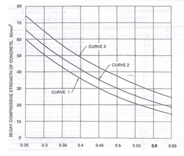

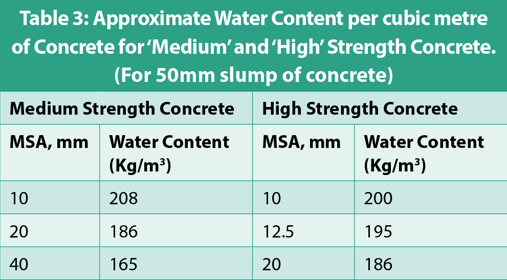
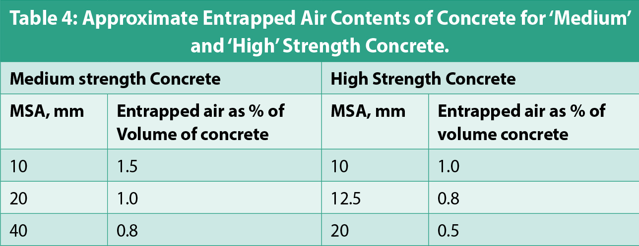
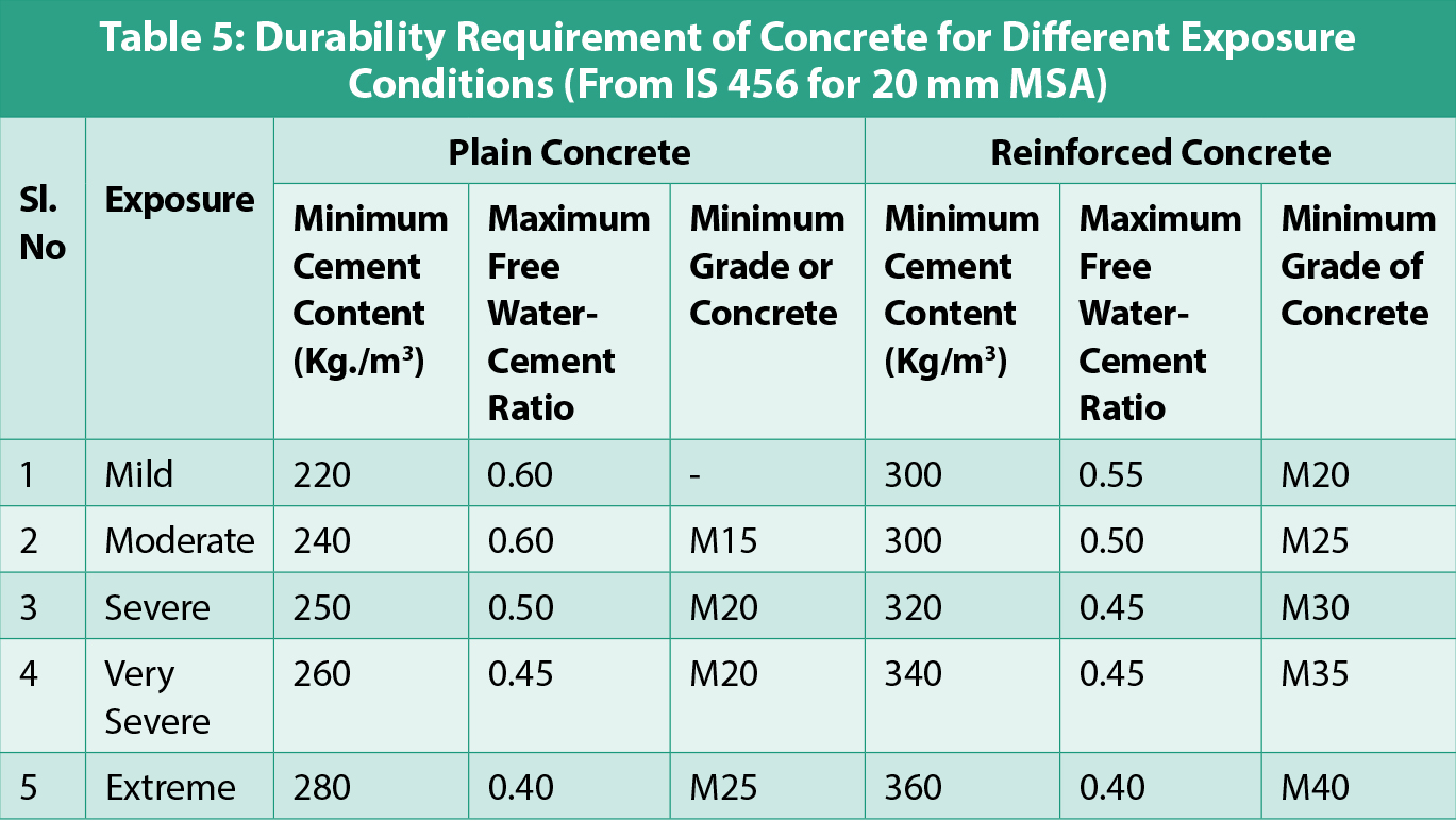

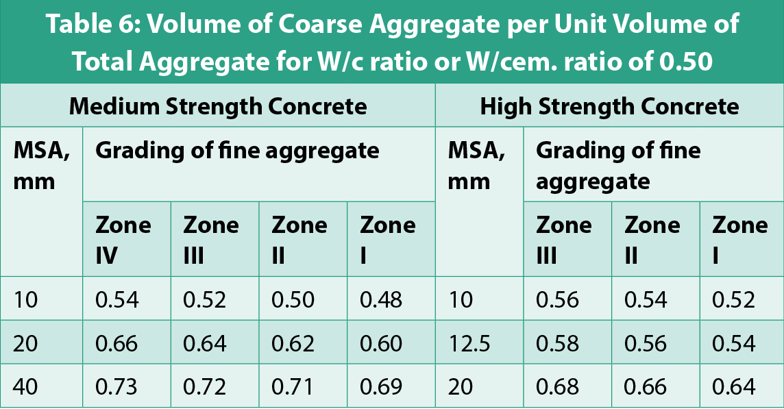


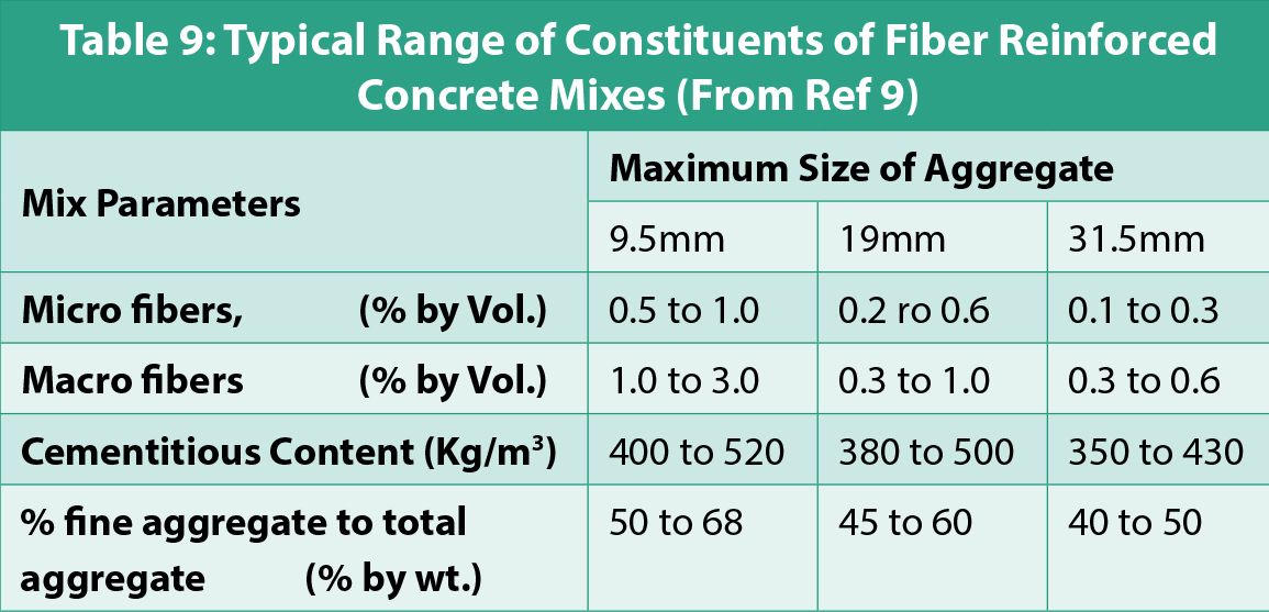
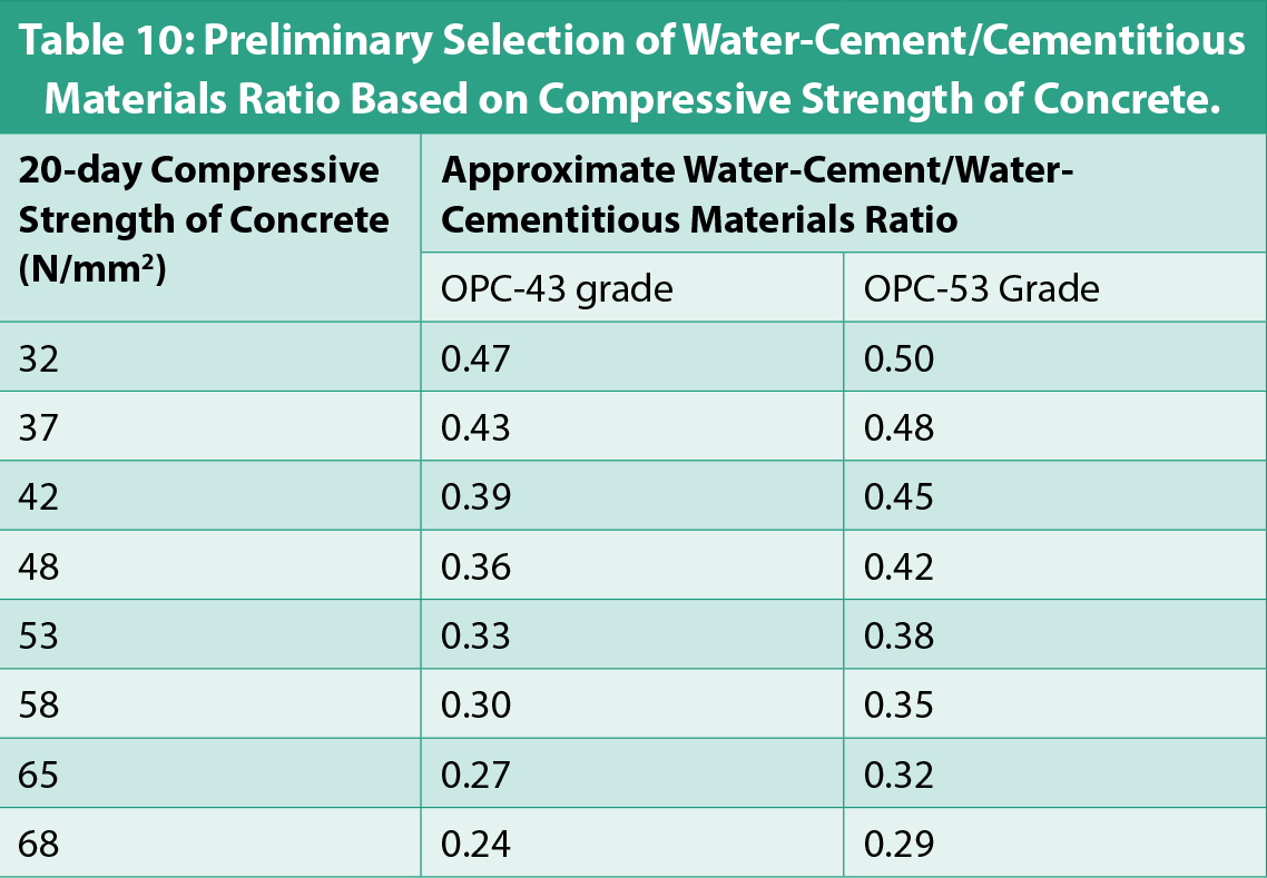

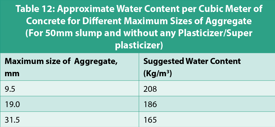
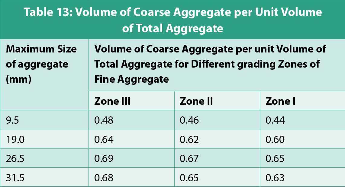
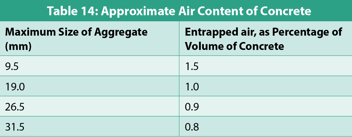
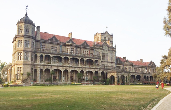

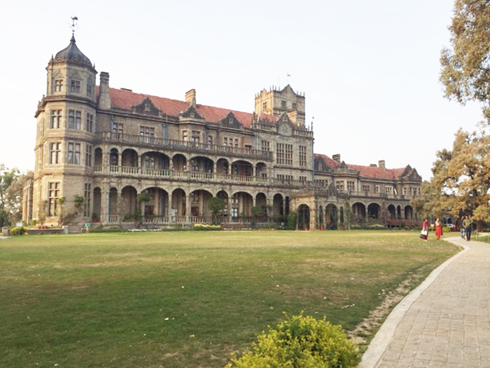
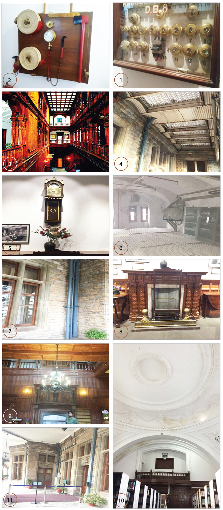

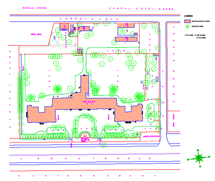
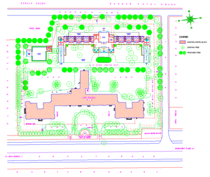
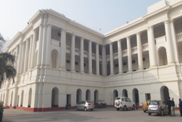
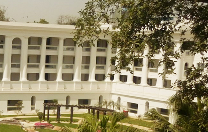
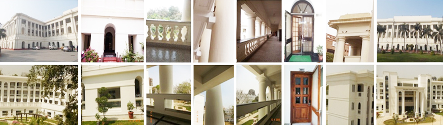

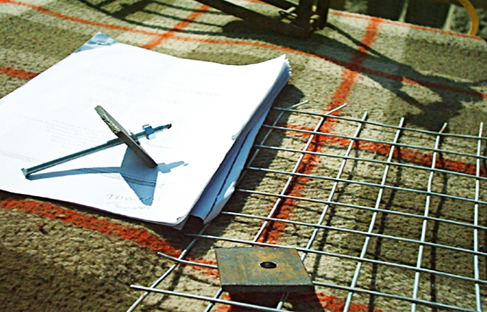
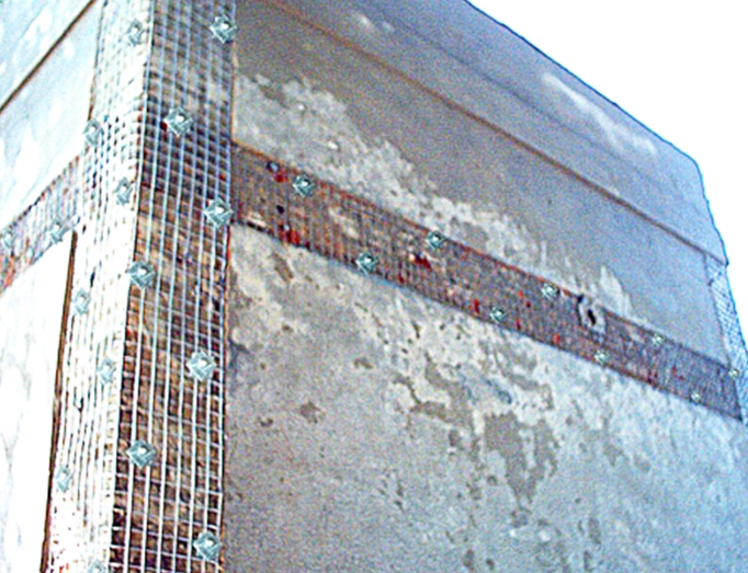
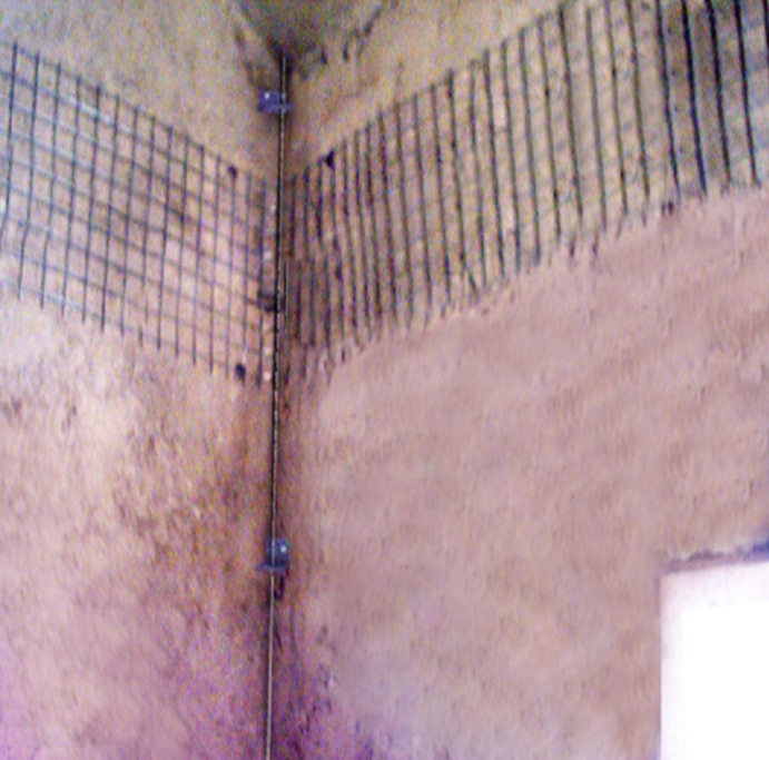


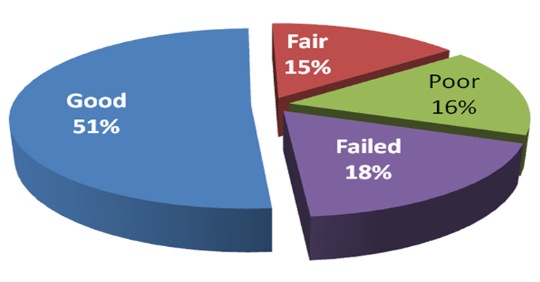

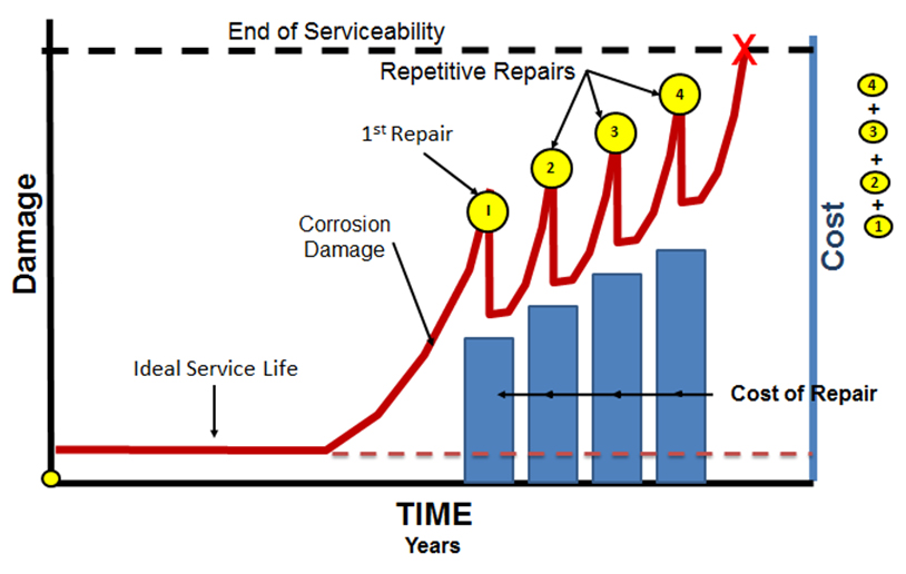


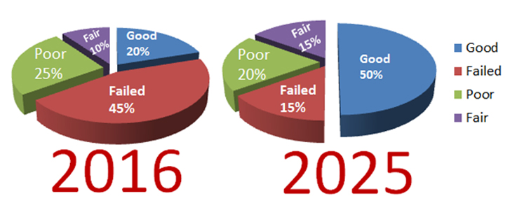
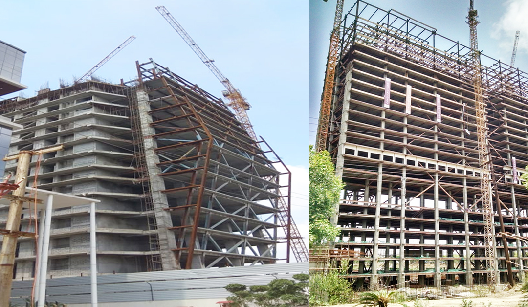


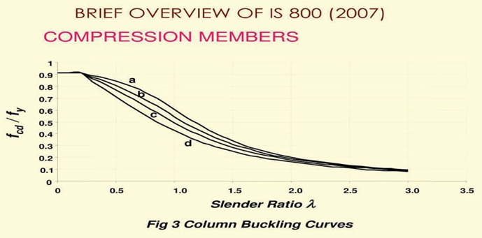
 Alphathum Tower, Noida
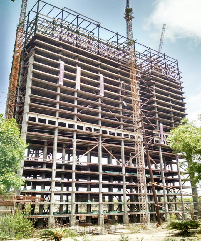 Mist Avenue – NOIDA
 H20 IT Park- Greater Noida
 Embassy Tech Village, Bangalore
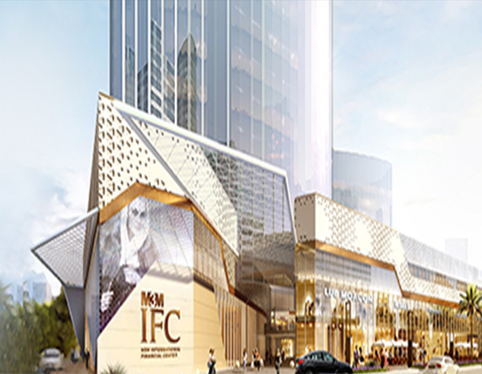 M3M-IFC, Gurugram
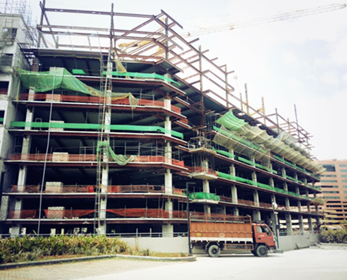 K. Raheja Corp, Hyderabad
 NICL Corporate Tower, Kolkata
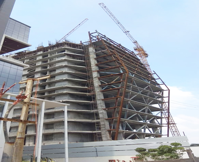 Windsor IT Building, Noida
 Multi level Car Parking, New Delhi