
Piling For Stronger Bridges Along Highways
Whenever and wherever road construction is undertaken, most probably, it will also involve building bridges. In most, if not all cases, since the load carrying capacity of the bridges are generally high, piling rigs or rotary drilling rigs as they are called, become a necessity rather than an option for drilling piles. In this regard, many constructing equipment manufacturers have introduced piling rigs in the Indian market. One such company is SCHWING Stetter India, which has launched XCMG range of piling rigs in the Indian market.
|
XR220DII XR220DII rotary drilling rig has a specially designed hydraulic retractable crawler chassis, super structure and large diameter slew bearing. It is used for foundation piling of highway and metro rail projects, port terminals, buildings, and other foundation construction, especially for civil engineering to drill holes in concrete cast-in-situ piles. Longer wheelbase gives it high stability to the terrain. Also, the Kelly-bar does not have to be removed during transportation. The transportation width and height are 3.25 m x 4.3 m, respectively. Compact size and light weight decrease the transportation costs and set-up time at the jobsite. It adopts an imported Cummins turbo charged engine with electro-control, which provides strong power and best in low fuel consumption in its category. Patented parallelogram type luffing mechanism achieves a wide range of work area. The mast is made up of high strength material with box structure design for high strength and rigidity to effectively guarantee the accuracy of drilling. Each articulated point adopts lubrication free bearing to make flexible rotation. Rotary drive, main winch and auxiliary winch have high output speed that improves the efficiency of work. Rotary drive is operated by a winch (cylinder) to crowd and extract, which is driven by hydraulic drilling motor. It is equipped with appropriate friction type or inner lock type drill pipe driven sets, which makes it convenient to work. The maximum drilling diameter is 2,000 mm with maximum drilling depth with friction/interlocking Kelly bar of 67 m/52 m. Operator cabin is of FOPS control cab with adjustable seat, air conditioning, operating, and working lights, windshield wipers. The console with all kinds of instrument and control handle is very user friendly for operation. Cabin is equipped with LCD colour display dashboard. The application of advanced intelligent control technology, CANBUS technology and virtual instrument technology makes human – machine interface simple and easy to diagnose and troubleshoot. It also indicates the perpendicular of the mast and drilling depth. Automatic real-time detection shows working record, fault recording, input/output signal of the online debugging and diagnosis, as well as the drilling mast limit, amplitude limit, main winding limit, filter clogging alarm, maintenance tips, all kinds of alarm information, etc. PLC control system can automatically or manually adjust the drilling mast inclination and perpendicular of the drilling mast. Either graphical or numerical, real-time dynamic display on dashboard is possible. |
 |
For further information,
visit: www.schwingstetterindia.com

Net-Zero Energy Buildings
By Amrita Batra
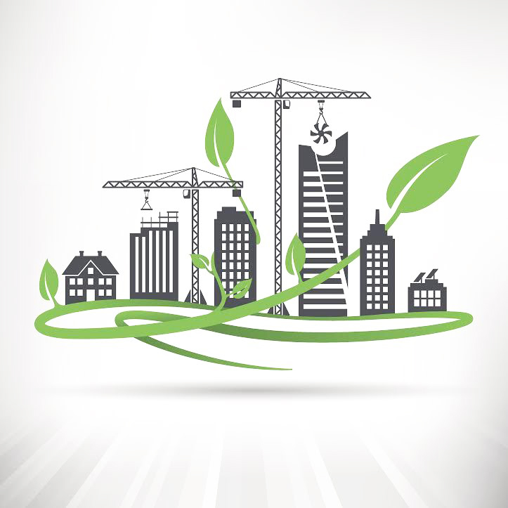
Across the country, property owners are seeking green initiatives and sustainability programs to minimize waste and reduce their reliance on natural resources while trying to keep their operational costs low. A new trend that is moving into the building sector involves creating zero-net energy buildings. Zero-Net Energy (ZNE) buildings are certainly a part of India’s future realty market. Governments, property dealers and realtors are embracing sustainable techniques at a fast pace during property construction.
Today, homeowners are enthusiastic about living in eco-friendly homes as it not only saves costs but also inspires a better way of life. A combination of an advanced building system and futuristic design make net-zero homes more energy competent and carbon-neutral. No doubt, Zero Net Energy buildings offer huge potential for saving energy!
According to the market research report published by P&S Intelligence, the global net zero energy buildings market share was valued at $896.6 million in 2018 and is expected to reach $2,106.6 million by 2024, advancing at a CAGR of 15.6% during the forecast period (2019–2024). The residential category is likely to show a faster CAGR during the forecast period, owing to increase in government targets and plans to achieve sustainable energy consumption.
Before we proceed, let us first clear our basics about ZNE Buildings.
What Are Zero-Net Energy Buildings?
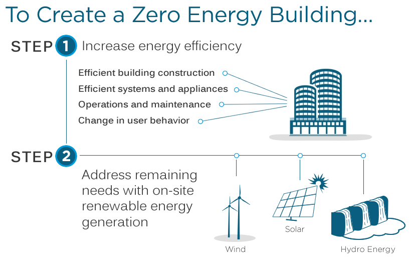
Zero-net energy buildings are a new wave of energy reduction and environment-friendly construction or renovation projects geared toward one goal: reducing the dependence of non-renewable energy that is produced off-site and delivered to the building. These are structures with no net energy utilization. This implies that the total energy consumed by the building on a yearly basis is nearly equal to the total renewable energy produced on-site or elsewhere by renewable energy sources.
In addition, building owners and facility managers try to reduce energy consumption throughout their operations so that the building uses less than the available on-site energy or equal to the amount of energy that is produced. The ZNE buildings add less greenhouse gas to the environment as compared to a similar non-ZNE building. These buildings can produce the same amount of energy it is using without compromising the daily life of the residents living in it.

By seeking renewable energy endeavours, buildings can save on costs that are spent exporting non-renewable energy from other areas across the country. It allows buildings to become highly efficient with less of an environmental impact. Currently, there are five types of structures that can qualify as being considered zero-net energy.
- Zero energy campuses consist of building sites grouped in a specific location that has renewable energy systems that are owned by the institution itself
- Zero energy communities are building sites that are grouped in a specific location that have systems that create renewable energy
- Zero energy buildings are fully or partially enclosed structures with exterior walls and a roof that has these renewable energy systems
- Zero energy portfolios are collections of buildings and sites where a single entity owns or leases renewable energy systems.

Technical Understanding Of Zero Energy Buildings
Zero-net energy homes are built with energy-conscious designs and include elements that can run without fossil energy sources. Other features include:
- Furnished with eco-friendly elements such as rooftop rainwater harvesting system that decreases the dependence on treated water.
- Solar panels, geothermal heating, wind turbines, and heat recovery ventilation systems are some of the techniques that are employed to achieve a zero-net-energy status.
In current times, while land constraints are pushing the trend of high rises and compact living, they are also exhausting a major portion of the total energy produced. Globally, buildings account for nearly 30% of the total energy-related greenhouse gas emissions.
Seeing that the global climate change is a burning topic at present, immediate action must be taken towards a reduced carbon future, making net-zero energy properties the cornerstones of the housing revolution.
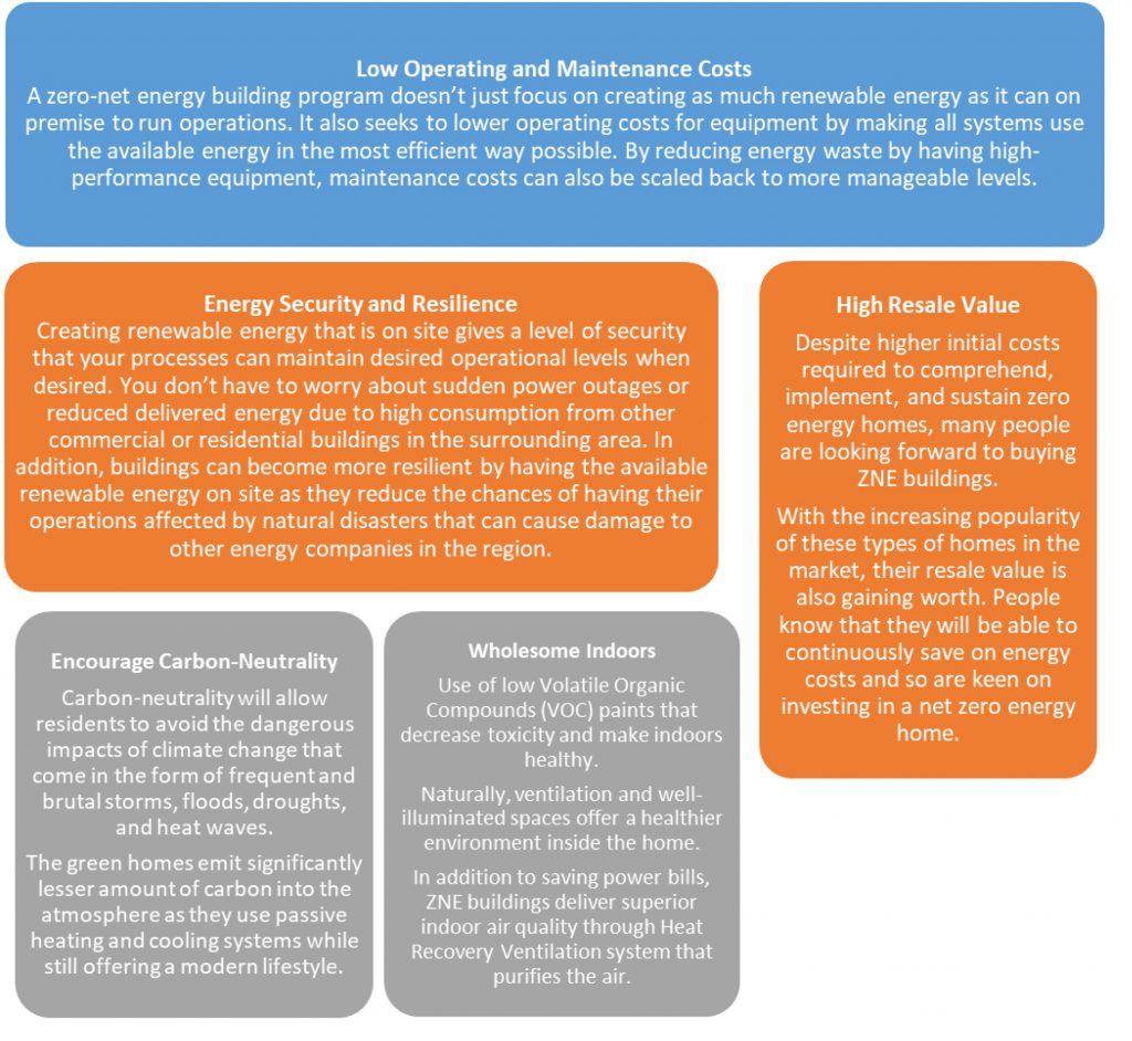
Advantages To Zero-Net Energy Buildings
There are many reasons why facility managers are seeking zero-net energy buildings in addition to seeking more environment-friendly operations. The types of long-term benefits can vary based on the building and operations. Some of the advantages you may seek if deciding to create a zero-net energy building:
A Worthwhile Endeavour In Reducing Energy Consumption
There are many ways that buildings can seek to become zero-net energy during the construction or renovation phase. Reduced plug loads, energy-efficient retrofits, and integrated designs as well as conservation programs can allow your facility to achieve this goal. Careful consideration and an evaluation of your facility can allow you to decide on the best initiatives and programs to seek out to lower energy consumption while making your building run more efficiently.
A green homeowner can save up-to Rs. 25,000-100,000 annually on the expenditure incurred on water, electricity, and society maintenance. This amounts to considerable savings at virtually no additional cost! With the decrease in the incremental costs of constructing green homes and the residents becoming increasingly energy-conscious, green homes will soon be available at similar prices as a regular house.
Not just individuals, real estate agents are also today more environmentally and socially aware. They seek new opportunities and choices that will benefit the planet, as well as the buyers.
As more than two-thirds of urban construction segment in India is yet to develop, ZNE homes seem a valuable opportunity to influence a paradigm shift in the direction of sustainable housing development while also allowing financial foresight and an enhanced sense of wellness on the whole. Indeed, a win-win situation!
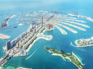
Palm Jumeirah, United Arab Emirates
Amrita Batra
Associate Editor
Civil Engineering and Construction Review
The Palm Islands are an artificial archipelago (a chain or cluster of islands) in Dubai, United Arab Emirates, one of the major commercial and residential infrastructure. Palm Islands consist of three artificial islands, Palm Jumeirah, Deira Island and Palm Jebel Ali, on the coast of Dubai, United Arab Emirates.
All three islands have similar palm-shaped structures, although the size of each varies. Nonetheless, they all follow more or less the same state-of-the-art engineering and construction procedures. The three islands share their date palm tree form with a spine, fronds, and a long trunk, a crescent shaped breakwater, sub-sea vehicular tunnel and monorail, sub-sea horizontal directional drilling (HDD) crossings on both eastern and western ends of the site, and pies on each side of crescent.

Stretching 5 km into the Arabian Gulf and shaped like a date palm, Palm Jumeirah is Dubai’s self-styled ‘eighth wonder of the world’. The over-the-top emirate is not just blowing its own trumpet though; this man-made island is one of the most audacious engineering projects ever undertaken.
Palm Jumeirah, in particular, has 17 fronds and a 1.5 km long trunk. The Palm, Jumeirah measures 5 km², has created 560 ha of land and has added 78.6 km to the country’s 72 km coastline. This is the biggest man-made island in the world and can even be seen from space.
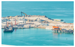
Construction
The construction of Palm Jumeirah began in August 2001, and is considered one of the world’s biggest undertakings. Unlike other previously man-made islands that are built from metal and concrete, Dubai’s Palm Islands are made from all natural materials – rock and sand upon Prince Sheikh Mohammed Bin Rashid Al Maktoum’s request. Although Palm Islands are artificial islands, the prince desired for a natural appearance that would blend into existing surroundings.
Construction workers lived on the fronds and in anchored cruise ships while building the island.
At the peak of construction, 40,000 employees were working on the project each day, turning 94 million m3 of sand and 7 million tons of rock into a leisure and lifestyle resort fit for the 21st century and beyond. Although five workers were swept away by a wave and one drowned, the designers at Nakheel believe the breakwater will protect the palm island from average gulf weather and even an enormous storm. They even suggest that villas barely 10 feet above sea level will be safe from the rising seas of global warming.
The palm islands are constructed from sand dredged from the sea floor. Palm Jumeirah is made from 3,257,212,970.389 cubic feet of ocean sand vibro-compacted into place. Vibro-compaction increases the density of loose sand by saturating it with jets of water and vibrating it with probes.
To get the complex shape just right, designers and contractors used Differential Global Positioning Systems (DGPS) to plot the palm and ensure the sand placement within 0.39 of an inch.
Palm Jumeirah is packed with villas and hotels. The buyers are a mixture of long-term residents, vacationers and speculators hoping to cash in on skyrocketing prices.

Breakwater Crescent
Divers surveyed the seabed and the workers constructed a crescent-shaped breakwater from blasted mountain rock. The Crescent of Palm Jumeirah stands a little more than 13 feet above low tide sea level and sits in 34 feet of water at its deepest point.
The breakwater crescent of Palm Jumeirah is about 11 km long and 200 m wide in cross section. It stands over 13 feet above low tide sea level and sits in 34 feet of water at the deepest point. The crest of the breakwater is 3-4 m above mean sea level. The seaward slope is one in two. The composition of the breakwater consists of coarse sand, quarry run, and 5-6 tonnes of sand. The seaside breakwater is protected by rubble mound armour. The lowest layer of the breakwater is filled with sand. Rocks weighing one ton were placed on top of the sand followed by two more layers of rocks.
A “toe” placed by a floating crane sits inside the Crescent. The breakwater also has two 328-foot openings on each side to eliminate stagnation in the 16 narrow, deep channels. These gaps allow water to completely circulate every 13 days. According to the Case Study No.1 Design of Palm, this is slightly different than the estimated average renewal times in another article, which stated at 10.1 days. The fact that the latter estimate was derived during the construction period can explain the different results. Water circulation around the fronds and open sea is critical for marine life, supply of oxygen and the removal of pollution. Furthermore, there is a retaining wall between the Crescent and fronds. Another layer of rock is placed in front of the wall to reduce overtopping quantity.
Reclaiming The Land
The next step was the land reclamation, which although extensively managed in countries such as the Netherlands, had never been attempted on this scale. The elliptical shape of The Palm also made accuracy difficult when placing the sand. As there were no fixed points of land to survey from, no place to ‘drive a stake in the ocean’, there had to be some other means of locating the positions to place the materials.
The engineers found their solution in DGPS, which allowed them to check the accuracy of the placement to within 1 cm. The sand – all 94 million m3 of it – was taken from the sea, not the Dubai deserts (7 million tons of rock also went into producing the first ever ‘curved’ breakwater).
Once dredged it was then vital to ‘settle’ the sand before it was built on – a natural process which normally takes millions of years. To build on unsettled land can lead to slippage – the Tower of Pisa being a good example. So, to hasten the settling, the sand underwent a process called vibro-compaction, which should mean there is no settlement greater than one inch in the next 50 years.
With the land reclaimed, the next step was to prepare it for occupation, with the installation of desalination plants, state-of-the-art vacuum sewerage wastewater treatment, underground power lines and the construction of a transport network including a monorail.
Sub-Sea Drilled Directional Crossings
The transport network was designed following three in-depth surveys by leading traffic consultant MVA. These resulted in an extensive road network, with a connection to the mainland by a gateway bridge, two bridges with five lanes in each direction and a six-lane underwater tunnel connecting the spine to the crescent (1.4 km long, 40 m wide and 25 m below sea level).
The Palm Monorail is fully automatic and driverless (although manned by an attendant) and has been developed by a consortium led by the Marubeni Corporation. The system carries up to 2,400 passengers an hour in each direction in four separate trains, each made up of three cars. The system transports a maximum of 6,000 people in nine vehicles.
The sub-sea vehicular tunnel and monorail connect the spine tip to the crescent and help facilitate utility services to hotel and leisure developments on the crescent. Six sub-sea HDD crossings are built at the eastern and western ends of the sites. The eastern crossing from Frond D to the crescent is 580 m in length at water line, with an average boring length of 680 m, while the western crossing is 700 m long at the water line with an average boring length of 800 m. In order to gain experience, Al Naboodah Engineering Services, the company in charge of installing 12 HDD crossings and 2 micro tunnels for electricity cable installation decided to first build the shorter eastern crossing. The pipes, located at a depth of 13 m to 16 m below the seabed in water depth ranging from 7 m to 14 m, provide for drinking water, telecommunications, wastewater and the discharge of treated sewage.

Challenges
The main challenges of the installation of sub-sea horizontal directional drillings on Palm Jumeirah specifically, was that there were close spacing between the bores (holes), changing soil conditions along the drilling alignment (fill/rock) and brackish (slightly salty) groundwater. To resolve the second problem, vibro-compaction technologies were used just like in the case with sand in the palm’s fronds themselves.
Besides the scientific challenges to this construction project, another challenge was the pressure to finish the islands in such a limited amount of time – 3 years. In order to keep ahead of schedule, the company constructing the islands, decided to start laying the sand foundation under the sea. Yes, time constraints forced both companies – the one constructing the breakwater crescent, and the one constructing the islands to complete both structures simultaneously. However, eight months into the project, it wanted to bring them above sea level. In April 2002, after 550 m of the breakwater crescent was completed, the company finally brought out the fronds.
Environmental Concerns
The construction of the Dubai Palm Islands has had a significant impact on the surrounding environment, resulting in changes to area wildlife, coastal erosion, alongshore sediment transport and wave patterns. Sediment stirred up by construction has suffocated and injured local marine fauna and reduced the amount of sunlight, which filters down to seashore vegetation. Variations in alongshore sediment transport have resulted in changes in erosion patterns along the UAE coast, which has also been exacerbated by altered wave patterns as the waters of the Persian Gulf attempt to move around the new obstruction of the islands.
References
- http://fac.arch.hku.hk/asian-cities-research/wp-content/uploads/dubai_impacts-study.pdf
- http://ijirse.in/docs/IJIRSE1407.pdf

Hong Kong-Zhuhai-Macau Bridge
World’s longest sea bridge
Amrita Batra
Associate Editor
Civil Engineering and Construction Review
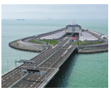
Measuring 55 km-long, including connecting roads, Hong Kong-Zhuhai-Macau Bridge (HZMB) is the world’s longest sea bridge and the longest fixed link on earth. It connects the west side of Hong Kong to Macau and the city of Zhuhai in Guangdong province, China. HZMB is a project of national and international significance; the desire was to ensure that it was constructed to the highest standards. The three Governments and the Authority completed the project with a target to achieve a 120-year design life for the crossing, with normal levels of regular maintenance.
The 55 km crossing consists of three cable-stayed bridges, boundary crossing facilities and link roads in the three cities, reducing the travelling time between Hong Kong and Macau/Zhuhai from an hour’s ferry ride to a 40-minute car journey. The functions of the bridge is to meet the demand of passenger and freight land transport among Hong Kong, the Mainland (particularly the region of Pearl River West) and Macau, to establish a new land transport link between the east and west banks of the Pearl River, and to enhance the economic and sustainable development of the three places.
Construction
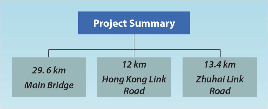
Preliminary design of the main bridge began in March 2009. The construction started in December 2009 and was completed in February 2018. The 29.6 km-long Hong Kong-Zhuhai-Macau Bridge (HKZMB) was inaugurated in October 2018. The total cost of the project was RMB 120 bn ($17.3 bn), while $87 m in funding was sanctioned for preliminary design and site investigation and $47 m for the preconstruction works initially. Hong Kong Legislative Council approved an additional HK$8.8 bn ($1.1 bn) for the project in April 2012.
The project included the construction of HKZMB, Hong Kong boundary crossing facilities (HKBCF), and a Hong Kong Link Road (HKLR). It also included related infrastructure development such as environmental protection, landscaping and drainage works, street lighting, traffic control, and surveillance systems.
The Hong Kong Port is located on a piece of reclaimed land of 150 hectares at the waters off the north-east of the Hong Kong International Airport (HKIA). The port also consists a passenger clearance building (PCB) which provides passenger clearance services, vehicle clearance plazas (VCPs) and public transport interchanges (PTI).
Several types of plants were used to provide greenery and colour in different patterns covering over 30% of the Hong Kong Port. In addition to emphasising the green landscape, the project contributed to sustainable development via creative engineering design, including independent sewage treatment system, district cooling system, eco-friendly building design, non-dredge reclamation method, among others.
Structural Details
The structure consists of three cable-stayed bridges, three artificial islands and one undersea tunnel spanning 55 km through the Lingdingyang channel. The route connects the three major cities of Hong Kong, Zhuhai and Macau on the Pearl River Delta – one of the world’s busiest shipping channels.
Formed from pre-stressed concrete box sections, the bridge was constructed using the balanced cantilever method. The total length of the crossing is approximately 41.6 km, of which 12 km is in Hong Kong territory and 29.6 km is in Guangdong. Forming a bridge-cum-tunnel structure, the bridge comprises a double three-track carriageway. It lands on two artificial islands created on the east and west of the Hong Kong special administrative region.
A scheme using a bridge and tunnel combination was adopted for the main part of the crossing within mainland territory. It comprises land and marine viaducts about 9.4 km in length, a 1 km tunnel and a 1.6 km road section.
The Promat team worked on the HZMB project for a number of years. The designers chose the RABT curve up to maximum 1200°C and determined the need for 25 mm thick PROMATECT®-H to be fixed directly to concrete according to the design and regulatory specifications. Approximately 290,000 m² of PROMATECT®-H and 8,000 tubes of 600 ml PROMASEAL®-A Acrylic Sealant are employed in the HZMB tunnel, making it one of the largest fire resistant board construction jobs for the tunnel segment business of Promat worldwide.
Challenging Iconic Design With An Innovative Construction Method
With a wavy roof designed to simulate undulating waves, the passenger clearance building (PCB) is an iconic building standing at the Hong Kong Port next to the airport.
To tackle the challenge of airport height restrictions, an innovative construction method was adopted to construct the PCB’s roof by using the prefabricated modules assembly method. The large-scale prefabricated modules were lifted one by one, pushed into position horizontally and connected together. Problems posed by the huge size, as well as the airport height restrictions, were overcome.
The method advanced the construction progress, enhanced the quality of works and reduced the risk of working at height. Different from the ordinary prefabricated modules, the roof modules were composed not only of structural steel frame, but also the pre-installed building services, as well as architectural builder works and finishes, saving on-site construction time.
Environmental Innovative Reclamation Technology
Non-dredge reclamation was the first-ever reclamation method adopted in Hong Kong. It greatly cut the amount of dredging and dumping of marine mud by about 22 million m3 and reduced the use of approximately half of the backfilling material.
This led to a lower impact on water quality and less marine construction traffic during the building stage. This helped to preserve marine ecology, especially the habitat of the Chinese white dolphins.

Long-Span Viaducts
The HKLR viaduct section features long spans as the carriageway crosses two navigation channels and Sha Lo Wan Headland, a designated Site of Archaeological Interest, where no construction works were allowed. A massive, bespoke straddle carrier was used to construct the long-span viaduct of 180 m in length. At the time it was erected, it was the longest, dual three-lane pre-stressed precast concrete bridge span in Hong Kong. The design minimised the visual and environmental impact and has also become a feature of the area, complementing the natural scenery of North Lantau.

Innovative Methods Adopted
The HKLR viaduct, mainly situated at open waters, is the first bridge in Hong Kong to adopt pre-stressed precast pier construction method and precast concrete pile cap shells to minimise underwater works. This ensured a safer working environment and eliminated tidal constraints.
Floating concrete batching plant was introduced, which was the first of such facilities in Hong Kong and significantly reduced the logistics and ensured the best quality of concrete produced.
The construction of two separate tunnel tubes of the HKLR to cross under the existing Airport Express Line (AEL) is one of the most challenging works for the HZMB project in Hong Kong.
As the AEL is an important railway link between Hong Kong International Airport and the central business district, the normal and safe operation of the AEL must be maintained at all times.
To ensure undisrupted operation of AEL during the tunnelling works, box jacking was adopted – the first time it was used at such scale in Hong Kong. It involved pushing the constructed tunnel box segments forward by hydraulic jacks sequentially in a ‘caterpillar’ motion, with a design jacking force of 19,400 tonnes – enough to lift 70 empty Airbus A380s in one go.

Challenges
Besides the large scale of the project, there were a range of physical conditions to be overcome during the construction of HZMB, including the sub-tropical weather, typhoons, heavy rain, and the hydrology and hydrodynamic aspects of the Pearl River estuary. Other factors included the geotechnical complexity of the site, the multiple navigation channels with high numbers of shipping movements and height restrictions for nearby airports. The HZMB also crosses environmentally sensitive areas — particularly the conservation area of the Chinese White Dolphin — which meant that high standards of environmental protection were set to minimise any effects on the marine ecosystem and fishery resources.
References
- https://www.arup.com/projects/hong-kong-zhuhai-macau-bridge
- https://en.wikipedia.org/wiki/Hong_Kong%E2%80%93Zhuhai%E2%80%93Macau_Bridge#Sections_and_elements