by Sawon Banerjee | Mar 8, 2021 | Construction Equipments
With A Factory-Fitted Leica Geosystems Machine Control System
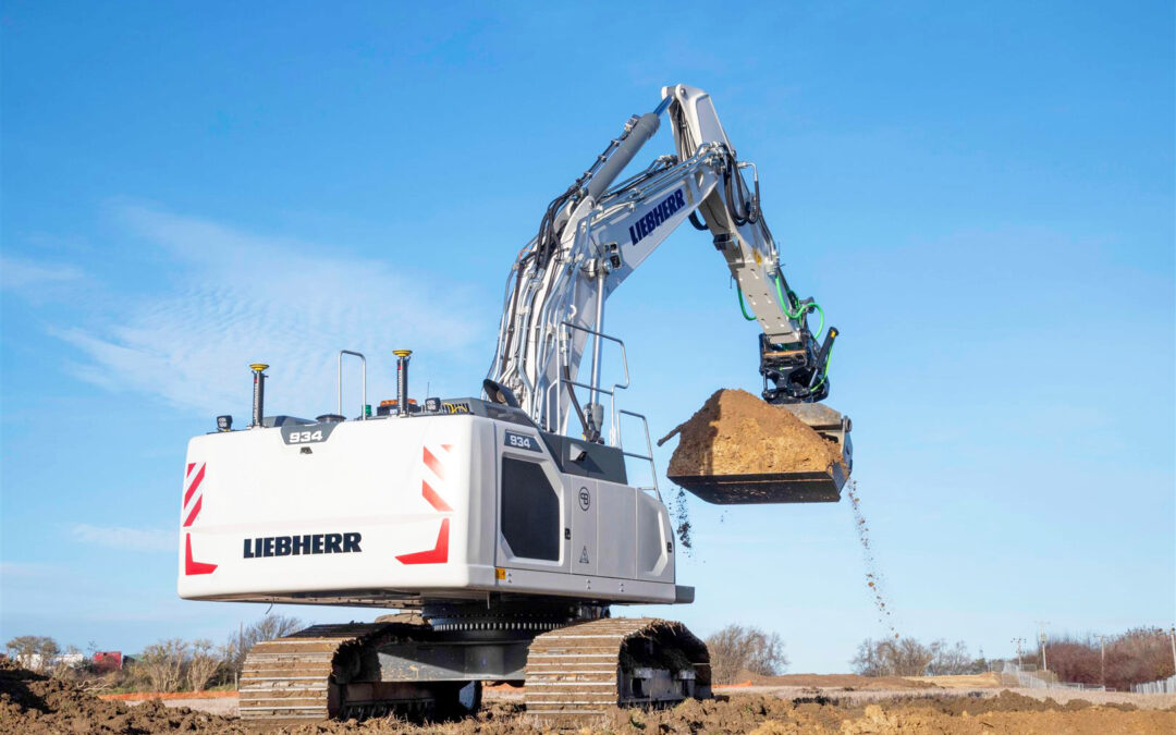
Liebherr and Leica Geosystems, part of Hexagon, have been partners in the machine control systems area since last year. A Liebherr R 934 G8 crawler excavator, the first hydraulic excavator with a factory-fitted Leica Geosystems machine control system, has been delivered to our customer Brad-Pave in Great Britain.
The partnership between Liebherr and Leica Geosystems allows Liebherr customers to purchase generation 6 and 8 crawler excavators and wheeled excavators with a factory-fitted 2D and 3D machine control system as an option. The first customer to benefit from this arrangement is a British company, Brad-Pave.
The generation 8 R 934 crawler excavator comes with the Leica 3D passive system and will be soon updatedd with a semi-automatic system featuring an automatic inclination / rotation function. According to the company’s director Paul Bradshaw, the machine control system is critical. It’s the key to accurate and effective work.
A Liebherr R 934 G8 Crawler Excavator, the First Hydraulic Excavator with a Factory-Fitted Leica Geosystems Machine Control System, has been Delivered to Customer Brad-Pave in Great Britain.
Choosing a Liebherr Machine for Quality and Service
It was thequality and expertise of Liebherr that persuaded Paul Bradshaw to opt for a Liebherr machine. Other factors tipping the balance in Liebherr’s favour were excellent service and several possible adaptation with the machine. These are the most important considerations for this British company. On its first construction site job, the R 934 was mainly used to dig a large drainage trench across a field. The machine’s power and responsiveness were entirely to the operator’s satisfaction.
The 7.1 tonne counterweight and 800 mm pads ensure good stability in all conditions. The machine has run up 350 hours on the clock since delivery. The director declares that he will definitely be coming back to Liebherr for his next purchase. This is our reward for high-performance customer service and for the advice and support provided with previous purchases of machinery and equipment.
The Entry into Partnership Detween Liebherr and Leica Geosystems Announced in March 2020 Enables to Offer Liebherr Customers the Expertise of Both Companies.
The Leica 3D Machine Control System
The R 934 crawler excavator is the first Liebherr machine with a factory-fitted Leica Geosystems control system. The entry into partnership between Liebherr and Leica Geosystems announced in March 2020 enables us to offer our customers the expertise of both companies, allowing to deliver more advanced and reliable solutions. This meant that Brad-Pave was able to purchase an excavator fitted with a Leica Geosystems semi-automatic 3D machine control system featuring an inclination/rotation function. According to Paul Bradshaw, the machine control system is the key to accurate and effective work. Factory installation has the advantage of ensuring high system reliability thanks to the expertise of the staff doing the installation work, in addition to reducing down-time on site. The company expects to increase its productivity with the help of this new built-in system.
For further information,
visit: www.liebherr.com
by Sawon Banerjee | Mar 8, 2021 | Construction Equipments
|
Mithilesh Kumar
Director,
Layher Scaffolding Systems Pvt Ltd
|
Layher Group produces high-quality scaffolding systems in Germany. Layher has worldwide presence with more than 40 sales subsidiaries. The products are being used by industries like construction, chemical plants, power plants, at shipyards and offshore. Now days for demanding and complex scaffolding applications – i.e. wherever conventional scaffolding technology falls short of optimal thus cost effective use, Layher Allround Scaffolding convincingly comes in with an unmatched range of advantages – unbeatably fast assembly, persuasive economic arguments and an extensive range of series-produced accessories.
More Possibilities – Layher Products and Services
Layher’s present product characteristics and services help customers achieve long-term success and increase the profitability of their companies. The Layher Allround Scaffolding has been established as a synonym for modular scaffolds on the market. The Allround Scaffolding offers unsurpassed versatility to be used in construction sites, chemical industry, power plants, aircraft, shipyards, event sector, theatres and arenas.
Allround scaffolding uses a simple, unique and bolt free connection technology. Sliding the wedge head over the rosette and inserting the wedge into the opening immediately secures the component. There is still sufficient play to secure the other end of the ledger.
A hammer blow to the wedge transforms the loose connection into a superbly strong structurally rigid one. The face of the wedge head is now precisely positioned against the standard. Connections in quick to assemble and spanner less scaffolding systems make a unique combination: providing structural strength immediately on assembly and subsequent ultimate force transmission while offering a choice of automatically right – angled or splayed connections with universal safety right from the start.
To transfer pulling force, every frame is secured by locking pins or bolts to each other. In this way the tower can be assembled on the ground and placed by crane.
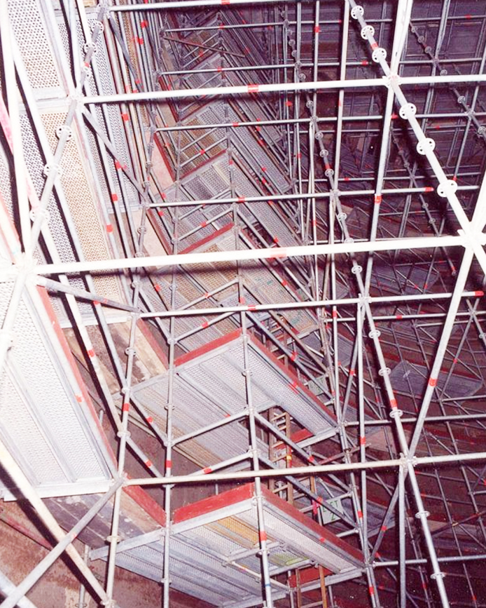
Layher Allround for External Maintenance of Tank
The Versatile Solution: Layher Allround Scaffolding
The proven combination of positive and non-positive connections in rapid bolt-free system technology with AutoLock function permits connections that are automatically right-angled, obtuse-angled and acute-angled as required, with built-in safety at the same time. Layher Allround Scaffolding has become a synonym in the marketplace for modular scaffolding.
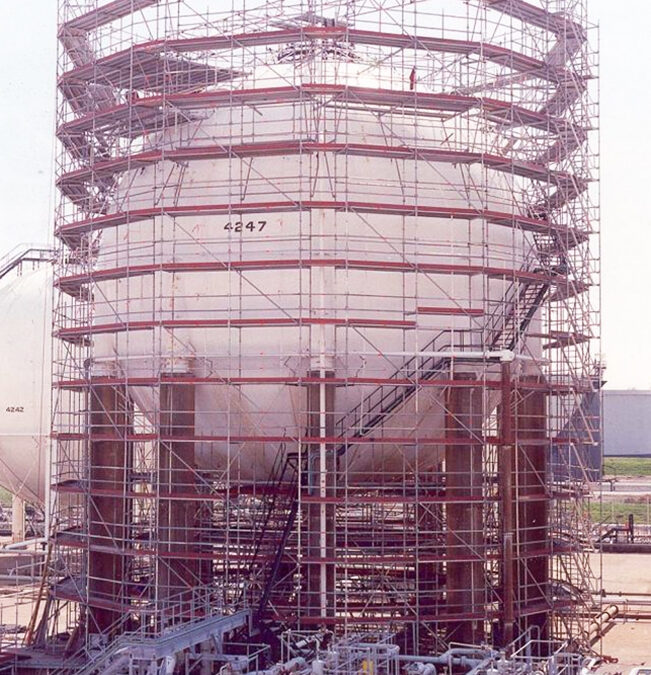
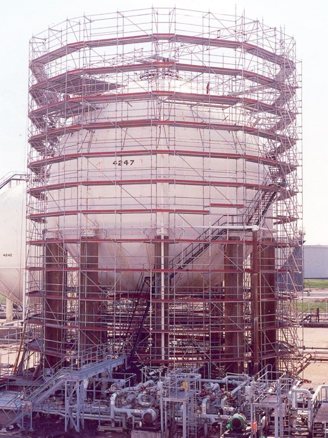
Application of Layher Allround Scaffold for Maintenance of Spherical Tank
Spheres are typically used to store below ambient temperature liquids and pressurized gases such as ammonia, propylene, LPG, butadiene, etc. Most (or many) spheres operate at low temperatures with -50°C (-58°F) as a lower limit. Gases are stored under pressure at a temperature lower than their liquefaction temperature.
The gas tank operated by Refinery is currently being refurbished, and corrosion prevention experts have to treat the entire surface of the tank. Safe access to all parts of the gas tank is assured with the use of a modular scaffolding system. By using Layher’s superior Allround equipment is only possibility to complete maintenance of circular tank.
The advantage lies in the speed with which not only the right angle can be automatically obtained with the system, but also variable angles can be achieved if required. This is done by fitting the ledgers in rosettes each with four holes at right angles, with four further larger holes (usually used for diagonal braces) being used to facilitate variable angles. This means that the erectors can also make connections at any angle as dictated by the conditions on site. The Scaffolder can easily, thanks to the eight possible connections in every connector, make adaptions quickly and optimally for almost any application.
Layher Allround for Internal Maintenance of Tank
These advantages ensure the optimum conditions for effectively enclosing the round tank with scaffolding. Allround Scaffolding was easily adapted to follow the contour shape of the sphere without difficulty. The erectors didn’t need to create complex tube structures, saw off tubes all the time, repeat measuring of connections or constantly align the upright elements. The wedge head provides an all in one simple yet stable connection, coupled with a logical assembly sequence and integral safety. Hot-dip galvanisation and certified quality assure Layher’s top-quality products are extremely long-lived.
Several work levels were required plus a lift going up 16 meters were required to be integrated into the scaffolding. The challenge set by this particular job was to follow as precisely as possible the double-curved surface of the tank. This was possible due to the extensive catalogue of parts Layher are able to offer.
Conventional anchoring to the tank was not possible. The scaffold erectors were only able to make connections to the all-round steel profile – the runner rail for the inspection ladders – at the tank’s “equator” using scaffold couplers. Above and below this anchoring level, the scaffolding was secured by all-round steel cables. A Layher landing-type stairway tower allowed convenient access to the scaffold at various levels.
The top lift of the scaffold at the top of the tank called for Layher’s expertise. Following the increasingly tapered scaffolding radius above the equator, Layher’s Technical Bureau designed a series of connected lattice girders to the topmost Allround standards which made them converge in tension-resistant form. The scaffolders then placed the structure on the highest point of the gas tank using four Allround standards.
This method has already proven its worth in time and money saving alone.
For further information,
visit: www.layher.co.in
by Sawon Banerjee | Mar 8, 2021 | Construction Equipments
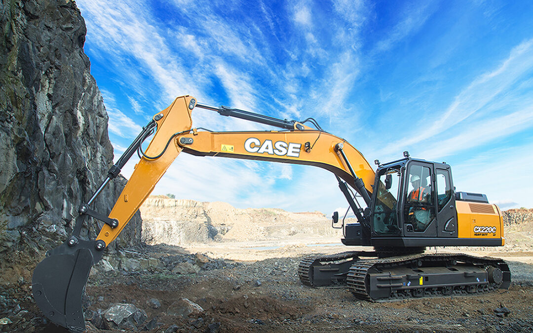
CASE India launched its first ever excavator CX 220C at the biggest construction equipment event in Asia – Excon 2019 in December. CASE Construction Equipment’s Crawler Excavator CX220C is specially designed for tough applications. This machine has been built for the Indian terrain and delivers maximum productivity, lower fuel costs and faster cycle times. A few salient features of the CX220C are:
High Efficiency
The operating weight of CX220C excavator is 22 tons and it is equipped with the fuel efficient FPT 6-cylinder electronically controlled engine. It develops a gross power of 117 KW (157 hp) and peak torque of 622 Nm at 1800rpm. This world-renowned FPT (Fiat Power Train), engine is designed to boost machine performance and optimize fuel economy. This engine delivers exceptional power and torque which reduces the transient time making the hydraulic system immediately reactive to any load. The fuel consumption in the excavator can be constantly monitored by the operator through the new ECO gauge function – that displays real time energy savings.
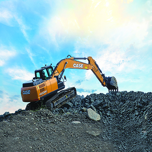
Precision and Controllability
The machine is highly suitable for stone quarry, road works, general construction, and earthwork. The proven CASE Intelligent Hydraulic System (CIHS) provides remarkable machine control with unmatched energy and fuel savings in all cycle time phases. Two variable displacement axial piston pumps with a regulating system are combined with the CASE main valve, designed in Japan for fine, precise, and efficient operations. The Hydraulic system is governed by a Machine Control Unit which collects input from pressure sensors located on the pumps, main valve, and pilot lines. The Machine Control Unit continuously dialogues with the Engine Control Unit to optimize machine output at any moment in any condition.
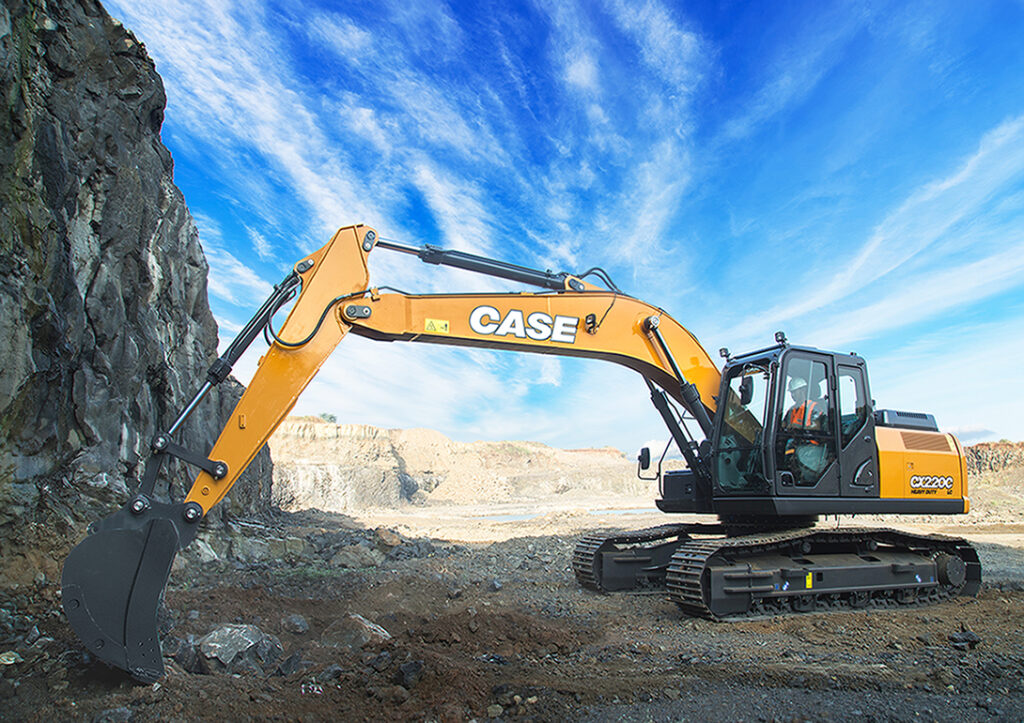
Reliability and Strength
Robust design with increased plate thickness on structures and attachments improves the durability of the excavator. The Boom and arm plate thickness has been increased by 33% and features Heavy Duty brackets and reduced tolerances which increases component life, thus minimizing downtime. The undercarriage structure features thicker structural plates and a sloped lower frame design.
The lower cost of ownership also comes with longer service intervals. Another plus is easy maintenance from the ground level for user comfort and faster service times.
Power and Versatility
The Excavator is an impeccable machine for every application, it comes with three available power modes and 10 auxiliary hydraulic settings. The power modes are:
- AUTO: for normal digging, grading, lifting and precision work. Power Boost always engaged.
- HEAVY: for heavy operations, always granting the best balance between productivity and fuel economy. Power Boost automatically engaged.
- SUPERPOWER: extra speed and power for the most demanding jobs that require maximum productivity. Power Boost automatically engaged.
Operators can store up to 10 auxiliary hydraulic flow and pressure settings to easily switch among different attachments with no need of any mechanical adjustment. This customized operation enables the machine to be highly versatile while maintaining power outputs.
Fast Cycles and Operator Comfort
The advanced hydraulic system offers higher breakout forces, improved swing speeds and greater swing torque, resulting in faster cycle times and 5% increase in productivity. Power boost function is automatically engaged. The electronic management of speed and power lowers fuel consumption and offers considerable productivity benefits in terms of outputs.
The CX 220C is equipped with CASE India’s renowned Telematics system for real time updates. The spacious HVAC Cabin comes with liberal legroom for a comfortable working environment. CASE India has also incorporated and ergonomically designed mechanical seat which has 8 different adjustments enhancing operator comfort and hence productivity. A system of vibration dampening is introduced which protects against whole body fatigue and gives maximum productivity. The cabin contains features like Auto Climate Control function and Air conditioning system with 25% more airflow and 8 vents for better efficiency during harsh summers; and an openable roof window to give better visibility on top. An integrated 7-inch LCD Monitor enables real time parameter monitoring.
For further information,
visit: www.casece.com
by Sawon Banerjee | Mar 8, 2021 | Construction Chemicals And Materials
Technology and 3D Tools Transform Concrete Construction Workflows. Find out what the Construction Process of
Tomorrow Looks Like.
|
Mr. Paul Wallett
Regional Director,
Middle East and India, Trimble Solutions
|
Amidst the Covid-19 gloom, there is finally good news on the horizon for the infrastructure and construction sector. The Indian government has rightly identified infrastructure and construction as priority sectors for investments in order to bounce back from the widespread economic recession that the pandemic has led to. This year’s budget has proposed `5.56 lakh crore capital expenditure for infrastructure, which represents a 34.5% increase over last year.
The ball is now firmly in the court of construction companies and as they gear up for accelerating the completion of projects both big and small, they can count on cutting-edge construction technologies as their ally. In fact, the ever-growing pressures for faster completion of all projects – from residential and commercial complexes to flyovers, highways, and airports – have necessitated the adoption of digital solutions to streamline workflows.
Nowhere is this adoption more critical than in concrete-based construction projects. Concrete is after all the most widely used construction material in India – and our nation is the second largest cement consumer in the world after China. It is the de-facto construction material of choice for most types of projects: from independent houses to tall residential complexes, from schools and hospitals to bridges and airports, and from metros to roads and highways.
Modern construction technologies, techniques and workflows have today emerged as powerful accelerators and enablers of efficiencies in all concrete-based construction projects. Still, the use of 3D modeling is perhaps the most important parameter that is key to improving overall project efficiency. There are many ways in which 3D tools transform the concrete construction process, and they can be pinpointed one by one, but the combined value of these tools is far more than the simple sum of its parts.
From pour planning to formwork and rebar, every step of the way is improved by working directly from a digital clone of the planned building, in the form of a 3D model, with manual tasks automated where possible.
Build it Virtually, Then Build it in Real Life
A constructible 3D model is the most realistic visualization of a concrete building before construction begins as it can highlight design inconsistencies before a single brick or slab is laid. 3D tools make it possible to create a full digital clone or a twin of the project that is being built, letting engineers and contractors work with accurate information instead of having to use guesswork for dimensions and element relations as with drawings and other documents
By using a precise digital clone of a building, concrete contractors are able to get the right dimensions and quantities calculation right the first time. A complete visualization without ambiguity transforms the project’s construction process because it eliminates the need for interpretation.
Further, each stakeholder involved in a project, from designers to structural engineers, from MEP contractors to fabricators, has access to all the information included in the model at all times. Because the model is digital, it is always up to date with the latest changes made by project owners. The digital 3D clone also allows everyone to view the building plan as it is at any stage, add information to it and extract information from it.
This makes the process as comprehensive as possible, because each stakeholder can base their work on much more data than if they were working individually. Information flows not just linearly, but seamlessly among all stakeholders. The result is a quality outcome, based on educated calculations and decisions. And when misunderstandings and rework are a thing of the past, productivity naturally goes through the roof.
A Fully Digital Workflow is Easier Than Ever
The integration of 3D tools into the concrete construction process has the potential to completely transform project workflows from beginning to end. However, and most importantly, it doesn’t mean that construction professionals will have to completely change their ways of doing their work or learn new things.
It actually means simply replacing manual tasks with automated ones and having a more intuitive, comprehensive and information-packed model to work from. The result is a streamlined process that benefits each and every construction professional and stakeholder, and a completed project that corresponds to the client’s needs and required standards in the best possible way.
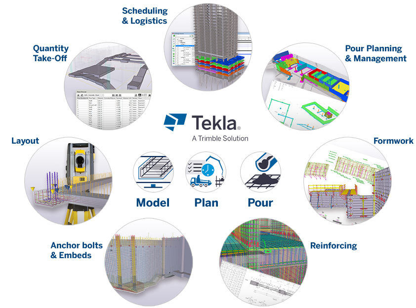
This integration is made easier with modern 3D tools like Tekla Structures, Trimble’s flagship modelling software for the construction industry. Tekla Structures offers 3D Building Information Modeling (BIM) right out of the box for concrete contractors and precast concrete producers.
The software generates digital 3D models (clones or twins) that are truly constructible and are purpose-built for the needs of concrete construction. As a case in point, Tekla Structures creates 3D models of pour information management, plan placement, quantify document formwork with intelligent, automated tools. It also coordinates adaptive and constructible reinforcement for any structure regardless of its complexity.
An important feature of Tekla Structures is an automated design-to-fabrication workflow. A model-based and fully digital workflow not only minimizes costly surprises and waste, but also improves efficiency and quality. It further ensures that the correct, error-free elements are delivered at the right place and on time.
Such digital workflows even help with streamlined project planning and execution. They allow project stakeholders to keep track of the progress and keep all parties of the supply chain well informed at all stages of the project. Utilizing the status information in the digital model is in fact a clear and effective way to coordinate the project and ensure its progress according to the predetermined schedule, as we can learn from a truly pioneering concrete project currently under construction in London.
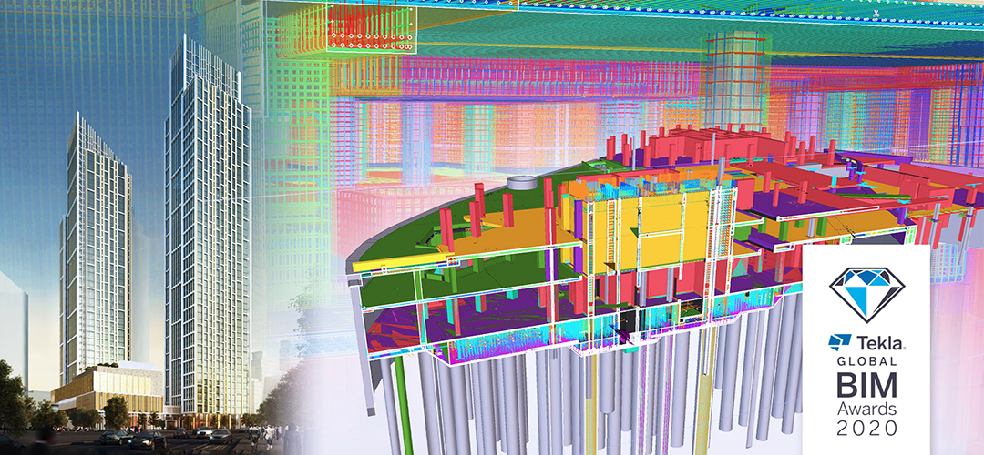
One Nine Elms: A Case for the Constructible
One Nine Elms is a skyscraper development under construction on the south bank of London’s river Thames. Upon completion in 2022, the development’s two towers (with 57 floors and 43 floors respectively) will combine luxury apartments, retail outlets and a five-star hotel. The project- two visually striking glass towers – the lower tower, which features the development’s hotel, is 160 meters high whereas its counterpart reaches 200 meters, making it the tallest residential building in Western Europe.
The One Nine Elms developers chose a top-down method for constructing the buildings’ three-floor basement for time and cost efficiency. “When the drawings for reinforced concrete construction are created in 2D, the chances of missing certain sections of rebar increase. This can cause huge time delays and additional costs for making the fixes”, says Solve Structural Design Technical Director, Barry Penniston, “3D modelling, such as that provided within Tekla Structures, allows for the proposed drawings to be checked quickly and accurately, ensuring full continuity before any concrete is cast.”
The re-bar design challenges were compounded by the fact that the core base raft for one of the buildings was constructed under very tight conditions. This meant that all equipment and materials had to be supplied through two small mole holes. With a Tekla 3D model serving as the single source of truth, the rebar detailers were able to identify and design around the congested areas, as well as avoid costly rebar clashes. This minimized the cutting and changes typically associated with a project of this nature, which in turn kept delays to a minimum and meant on-site work was safer. All this was especially critical amid the tight conditions and considering the size and complexity of the subsequent continuous pour for the taller tower.
Many similar projects in India and around the world by other construction industry leaders have amply demonstrated the value advantage of using 3D tools in general and constructible BIM in particular in delivering concrete-based projects faster and within budgets. The business case of enabling fully digital and model-based workflows for construction projects is well established today, and the gains are far too significant to be overlooked by anyone – least of all the forward-looking construction companies in India.
For further information,
visit: www.trimble.com
by Sawon Banerjee | Mar 8, 2021 | Construction Chemicals And Materials
|
Mr. L Sivasankar
Sr. Vice President
Taisei International
|
India’s road system has grown rapidly over the past decades, and it continues to expand. The contribution by M/s. TAISEI INTERNATIONAL through their INTERNATIONALLY RECONGONISED PRINCIPALS have introduced several latest art of technology, Non destructive, Non nuclear, on- spot testing, measuring, quality control, road safety & surveying instruments, which are regarded as global leaders in their respective product categories.
This introduction enabled the infrastructure industry to keep phase with the volume of work without any sacrifice on the QC /QA.
The products like ARRB Australia make Network Survey Vehicle Hawkeye 2000, Grontmij Carlbro make Falling Weight Deflectometer, Delta Denmark make Retroreflectometers, Transtech USA make Non Nuclear Pavement Quality Indicator Model PQI 380 etc., have not only proved its efficacy in India but, are also followed as a mandatory standard in India like any other developed countries.
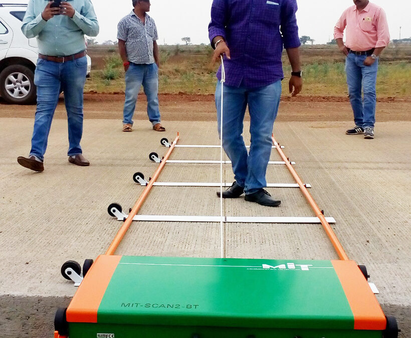
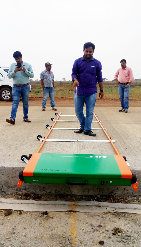
MIT-SCAN2-BT is the new introduction by M/s. TAISEI INTERNATIONAL together with their German principals M/s. MIT Mess- und Prüftechnik GmbH which has been successfully field assessed and is likely to be an indispensible equipment for both execution as well as quality control officials.
The geometrically increasing thousands of kilometers of new concrete roads are the lifelines of a growing economy. Their long durability – based on high quality paving – is essential for the effectiveness of the young road network and an indicator of the capabilities of the Indian construction industry.
But quality in road construction is no coincidence and can be measured comprehensively, objectively and reproducibly using modern electronic measuring systems. The aim of contracting authorities is to improve the road quality in terms of sustainability, safety and cost-efficiency in construction and maintenance. This is increasingly reflected in their demand for additional quality documentation. Construction companies, on the other hand, face increasing challenges regarding speed of construction, cost effectiveness and quality requirements.
Joint zones, in particular, are critical areas with regard to the durability of a road. As the joints absorb the movements of contracting and expanding concrete slabs as well as the load of the traffic, they are exposed to stresses and strains. Dowels are embedded in concrete pavements to transfer the load across the joints and reduce their faulting. The proper alignment of dowel bars is critical to ensure the long-term intactness of the joint zone. If the bars are not adequately centered under the joint saw cut, the bars may not be effective in providing load transfer. Misaligned bars can lock up the joints and prevent them from opening and closing freely.
A dowel position scanner of the German manufacturer MIT Mess- und Prüftechnik GmbH(MIT) addresses the need to verify the placement accuracy of dowel and tie bars in concrete highways. MIT develops non-destructive measurement systems used for quality assurance in road construction. The company advances its NDT systems continuously to meet the increasing requirements of quality testing. Thus it has become a reliable partner of the construction industry around the world.
The dowel position measurement system MIT-SCAN2-BT was introduced in India in 2016 and provides the rapidly advancing Indian road construction with a fast, comprehensive and non-destructive method for the assessment of dowel positions.
Dowel position testing can be used for the self-monitoring of contractors as well as the quality assurance for acceptance purposes. Requirements for the acceptance are shown in ASTM E3013/E3013M-15, in various national standards, and since 2017 in the fifth revised version of the Indian Code of Practice for Construction of Jointed Plain Concrete Pavements (IRC:15-2017).
The dowel position scanner operates on the basis of pulse induction method. The device makes use of the magnetic properties of the dowel bars. By means of a pulsating magnetic field, it induces eddy currents in the bars. The resulting electromagnetic response field is measured at a fast sampling rate by an array of sensors.
The measurement process is very straightforward. A mobile rail system is placed above the joint to be assessed. The measuring trolley is then pulled over the rails along the joint. It is controlled via a mobile computer that communicates wirelessly with the measuring device. During the measurement run, the computer displays the signal received and the distance covered. Due to automated signal analysis, the number of dowels as well as their spatial position and orientation are determined within a minute.
Different parameters that describe the deviation of a bar from its prescribed positions – namely the depth deviation, the lateral translation, the vertical and the horizontal rotation – are computed with a tolerance of just a few millimeters. Thus this testing equipment is not only easy to operate, fast and non-destructive but also highly accurate and therefore altogether very economical.
This becomes particularly clear in comparison with destructive methods such as core drilling that impair the road surface, only allow random measurements and are very expensive to carry out. But also the advantages compared to the non-destructive method, which is based on the reflection of electromagnetic waves (ground penetrating radar), are obvious.
The speed of propagation of the radar waves is influenced by the properties of the concrete, such as moisture, and needs to be determined by the use of a reference drill core before starting measurements or when deviations in the concrete’s properties occur. This severely limits the usability of ground penetrating radar on wet roads and during the curing process. In contrast to this, MIT-SCAN2-BT can be used on walkable ground, shortly after the concrete has been paved and is therefore also useful for the adjustment of the equipment. Thus, the measuring system is also used to improve the dowel bar positions during the paving process. Existing GPR-systems are less specialized in the specific measurement task and offer therefore merely time-consuming, non-automatic analyses, whereby the lateral displacement of the dowels cannot be calculated.
Parameters such as the lateral translation of the dowels are quite important. Installation errors, which experience has shown to be frequently observed, are joint cuts that do not coincide with the center of the dowels. The consequence of a faulty joint cut is the uniform lateral displacement of all dowels in relation to the cut joint. Another typical installation error are alternating depths that arise in connection with the compaction of the concrete and in connection with its consistency. The detection of such systematic incorrect positions is only possible through the comprehensive, non-destructive measurement of the dowel positions. MIT-SCAN2-BT enables efficient inspections of large road stretches in one workday, which makes it a cost-effective instrument for contractors as well as for authorities.
The pulse induction method has been well-proven in other measuring devices of the German manufacturer, who also developed an instrument called MIT-SCAN-T3 for the non-destructive and accurate measurement of thickness layers in asphalt and concrete pavement like several superposed layers of asphalt pavement as well as unbound courses of the lower pavement structure (frost protection layer and aggregate base layer). Areas of use include new road construction, sub-base construction as well as pavement inspection and rehabilitation of existing roads. However, a prerequisite is the installation of a standard metallic reflector made of aluminum or steel at the base of the pavement layer to be measured. It serves as an antipole. Layer thickness can be determined directly during paving (self-monitoring) or later as part of control inspections (external monitoring) performed for acceptance of construction work and calculation. To conduct a measurement, the MIT-SCAN-T3 is simply pushed over the measuring site. Within seconds, it accurately determines layer thickness. This way, based on a larger number of measuring sites, pavement thickness can be measured extensively and effectively. In Germany, MIT provides interfaces for the inclusion of layer thickness data in a cloud-based building information management. In this way, it participates in the optimization and automation of building processes, and thus, the future requirements of road construction can be met already today.
For further information,
visit: www.taiseint.com