A Hydraulic Wonder

The Rolling Bridge is a kind of curling moveable bridge, completed in 2004 by Heatherwick Studio, which was commissioned in 2002, to design a pedestrian bridge to span an inlet as part of the Grand Union Canal office and redevelopment of Paddington Basin, London. The new bridge would offer an access route for workers and residents across a narrow inlet of the main canal, while also letting the boats pass when required.
Construction And Design
The property development company Chelsfield invited the Heatherwick studio to design one of three bridges, as part of redevelopment process. The studio, founded by acclaimed English designer Thomas Heatherwick, could have selected a more traditional option, such as a swing bridge, a lifting bridge, or a rigid retractable bridge. But, Heatherwick had the vision “of a steel pedestrian bridge rising up over a canal inlet and curling into a ball on one side to allow passing water traffic through.” Today, this structure is the only bridge of its kind in the world.
The idea of the design is inspired by the dinosaur Apatosaurus from the movie Jurassic Park, and how the animators replicate the animal’s flesh and copy the natural movement and flexibility with steel mechanisms covered in silicon rubber.
The Rolling Bridge, designed to open in 180 seconds, employs a curling action to move forward and backward across the distance of the canal. The extension and retraction is describable as a magnificent organic motion, similar to a leaf unfurling, or a caterpillar curling up, or the fingers of a human’s hand closing to form a fist. Moreover, the bridge closes in near silence, which adds to its elegance, and can also be stopped at any point through its extension or retraction. Once fully retracted, it looks like a sculpture rather than a bridge, and like an old water wheel.
Extensively modelled in CAD and exported to Robot analysis software, bridge models were employed for the stagnant examination and authentication of the geometry. Also, using animation tools, a virtual working model was created to validate the motion and permit component measurements in any arrangement.
The structure wasn’t constructed on-site; it was built at Littlehampton Welding on the Sussex coast and then, floated through the Grand Union canal, before being raised into place at Paddington and attached to the hydraulic system which powers its movement. Besides, to develop the final design as planned, the studio closely worked with the fabricator.
The bridge was originally planned to unfold across the canal every Wednesday and Friday at midday, and every Saturday at 2 p.m. Now, however, its operation is limited to Fridays at noon.
Structural Details
The Rolling Bridge is about 39 feet (11.8 metres) long and spans an 8.5 metre canal inlet; however, its inventive design makes up for its miniature stature. The structure comprises eight timber-and-steel triangular sections hinged at the pavement level and linked above by two-part links that can be collapsed to the deck by hydraulic cylinders arranged vertically between the sections. When extended, it resembles a regular steel and timber footbridge.
The Rolling Bridge Under-Construction
Each bridge segment is made-up in three sections, two welded side frames and the deck. It was initially planned that the segments would be fully welded frames, but to achieve the required machining tolerances, a bolted connection was introduced between the side frame and deck.
Interestingly, the structure is attached to only one bank; the remaining seven bays, powered by hydraulic rams, push the handrails upwards to allow the passage of boats. The movement activates the hydraulic pistons and set into the bridge’s balustrade, causing the triangular sections to raise and draw near. As the bridge opens the handrail pushes through the horizontal, this initial movement momentarily extends the top boom causing the bridge to arch. As this happens, the bridge curls up as it moves towards the bank. The two ends eventually meet, creating an octagonal shape measuring one half of the waterway’s width at that point, and then rolling it back to form an enclosed ball.

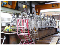
Construction at Littlehampton Welding
In its unrolled ‘bridge’ state, the handrails function as the top boom of a simple truss. They are pulled below the horizontal to lock the bridge in position, which guarantees that a small component of the compression load is directed downwards ensuring the stability of the bridge under load. The handrail is afforded lateral restraint by the U frame nature of each segment. To relieve the large forces that would otherwise be generated by the movement of the handrails, the ‘fixed’ segment of the bridge is mounted on a rocker permitting the essential rotation.
The movement of the handrail is followed by the upward movement and the structure transforms from a simply supported truss to a cantilevered truss with the obvious load reversal between top and bottom booms. During this time, the hydraulic rams act as an integral structural component with several segments again witnessing load reversal as the bridge rolls over centre.

Triangular Sections
In the enclosed ball condition, stops mounted at the top of each hydraulic cylinder bear the static load of the bridge. The hydraulic team achieved the delicate control of the bridge through pure hydraulics. A hydraulic pump drives a master cylinder, which is mechanically linked to 14 slave cylinders. In turn, the slave cylinders drive the bridge cylinders. Ensuring all the cylinders are driven at a constant rate is significant for the operation of the bridge.
Polytetrafluoroethylene (PTFE) infuse dry bearings were used for dimensional stability, longevity and a maintenance free operation. The bearings and (Duplex) stainless steel pins were fitted to a tolerance +/-0.016 mm, with a tolerance between pin centres of just +/-0.15 mm.

It Resembles a Regular Steel and Timber Footbridge
Challenges
In addition to the usual bending, shear, deflection and dynamics checks common to all structures, the unusual nature of the bridge directed various interesting and esoteric engineering challenges as the design had to compete with the ever-changing geometry and load conditions related to the movement.
- The project required precision bearings and pins with challenging fabrication tolerances.
- Fabricated with grade S355 hollow section steel tubes, the structural frame has a hardwood timber deck to both faces of the base.
- The void within the deck is used to route the hydraulic feed and return hoses to power the rams.
- The fabrication proved equally challenging, as to achieve the geometry in bridge configuration, and more especially in its closed form, required fabrication tolerances were normally found only in the domain of mechanical engineering.
- When closed, the handrail components converge in the centre of the bridge with a little less than 10 mm clearance between them.

Attached to One Bank
“Rolling” As A Name
Despite the implication of its name, the “Rolling” bridge is more accurately described as “curling”. While its designer refers to this particular structure as “The Rolling Bridge” on his website, this should perhaps be considered as the name for this particular bridge rather than a term to refer to its type, which could be more correctly described as a “curling bridge.” At present, this curling bridge is the only one of its type known to be in existence.

Awards
The Rolling Bridge won a number of awards, including an Emerging Architecture Award, and a Structural Steel Award, with the judges noting that the bridge was a “joyful addition to the [Paddington Basin] development area that has all the appearance of a Leonardo sketch when in the ‘rolled’ position.”
References
- 1. heatherwick.com/project/rolling-bridge/
- en.wikipedia.org/wiki/The Rolling Bridge
- www.visitbritain.com