 |
Murari Ratnam Former Director Central Soll and Materials Reseach Satiton, Ministri of Water Resource, Govt of India , New Dehli |
Introduction
The construction activity in India has been increasing geometrically since independence. During this period, we have created substantial infrastructural assets in terms of buildings, bridges, sport stadiums, dams, etc., which are lifelines for the civilized society. Presently, there are about 5,100 large dams in the country, one-third of which are concrete and masonry dams. Apart from the large dams, India has innumerable major and minor structures, which have been created through huge investments.
Several large dams in India are more than 100 years old and require constant maintenance. It is therefore essential to maintain them in functional condition. As numerous dams are in a state of distress, a systematic approach is required to deal with such problems. The identification of the causes of deterioration and consequent repair/rehabilitation strategy at optimum cost is essential. The current paper thus, focuses on issues pertaining to repair and rehabilitation several large dams in India.
Repair, Rehabilitation Or Retrofit?
It is important to distinguish between repair, rehabilitation and retrofit of a structure. All three terms refer to modifications carried out on a structure, but in different contexts; while retrofit and rehabilitation may involve addition of new structural elements or a change in the structural system, repair is restricted to the built-in system.
Repair: Repair refers to the action that improves the functionality of components in a structure that have been rendered defective, deteriorated or damaged due to some cause. The purpose of repair is to rectify the observed defects and bring the structure to its original architectural shape and intended purpose. This action is generally non-structural in nature; it does not guarantee structural safety. In fact, a repaired structure may be deceptive in a manner that it will appear to be in a good state and give the occupants a false sense of safety.
Rehabilitation: Rehabilitation refers to structural interventions that improve the strength of the components in a structure that are either deteriorated or damaged; the rehabilitation process is intended to regain the original strength of these structural members. For example, in the event of a fire in a structure, rehabilitation work is undertaken to replace or strengthen the damaged structural members. Such intervention provides only the original strength of the structure and is appropriate if the original strength provides an adequate level of safety. Further, the term restoration is sometimes interchangeably used with rehabilitation.
Retrofit: Retrofit specifically aims to enhance the structural capacities (strength, stiffness, ductility, stability and integrity) of a structure to mitigate the effect of a future earthquake. The term seismic retrofit is used in the specific context of enhancing the resistance of a vulnerable structure to earthquakes. Sometimes, the terms ‘seismic rehabilitation’, ‘seismic upgrading’ and ‘seismic strengthening’ are used in lieu of ‘seismic retrofit’. It is not necessary for the structure to be deteriorated or damaged for retrofitting to be performed.
Causative Factors
Concrete dams could be deteriorated due to one or more of following causes and the distress may manifest in terms of cracks, seepage, leakage, pit formation, surface abrasion, etc. The causes are discussed below in detail.
Design/Construction Deficiencies
This includes inadequate design criteria adoption of incorrect or unsafe parameters based on deficient investigation, inadequate investigation leading to erroneous assumptions, under estimation of design floods and seismic potential. Several old dams were rehabilitated by strengthening, providing additional spillway capacity, widening from d/s side, providing u/s impermeable barrier, etc. for correcting different kinds of design/construction deficiencies.
Erosion
Erosion of concrete occurs by three forces namely, cavitation, abrasion, or chemical action.
Cavitation Erosion: Cavitation is the formation of bubbles or cavities in a liquid. In hydraulic structures, the liquid is water, and the cavities are filled with water vapour and air. The cavities form where the local pressure drops to a value that causes the water to vaporize at the prevailing fluid temperature. Moreover, the concrete surface irregularities trigger the formation of these cavities; the pressure drop caused by these irregularities is generally abrupt and is caused by local high velocities and curved streamlines. The cavitation bubbles grow and travel with the flowing water to an area where the pressure field causes collapse; the cavitation damage can begin at that point leading to pitting of concrete.
A few examples of dams that experienced cavitation erosion: In USA, Dworshak dam, Glen canyon dam, Lower monumental dam, Lucky peak dam, Yellowtail afterbay dam, Keenleyside dam and Hoover dam; in Iran, Karun dam; in Venezuela, Guri dam; in Brazil, Jupia dam; in Pakistan, Tarbela dam.
 Glen Canyon Dam |
Abrasion Erosion: Damage results from the abrasive effects of waterborne silt, sand, gravel, rocks, ice, and other debris impinging on a concrete surface during operation of a hydraulic structure. Further, the hardness of the particle, quantity of particles impinging on concrete surface, quality of surface and velocity of water affect the extent of damage. Abrasion Erosion is readily recognized by the smooth and worn-appearing concrete surface. Spillway aprons, stilling basins, sluiceways, drainage conduits or culverts, and tunnel linings are the most susceptible to abrasion erosion.
Few examples of abrasion of dams: In USA, Espinosa irrigation diversion dam, Kinzua dam, Nolin lake dam, Pamona dam, Red rock dam and Kentucky dam; in Pakistan, Tarbela dam; in Bangladesh, Karnafuli dam; in Brazil, Ilha Solteira dam; in India, Maneri dam and Ichari dam. |
| Erosion By Chemical Attack: Aggressive water includes soft water, water containing sulphates, chlorides, acids, etc.; the concrete may be affected by any one or a combination of these factors. Soft Water: Because of high dissolving capacity, soft water is known to leach lime from the binding material over a period, resulting in increase in seepage, drainage flows, uplift and a decrease in loss of strength. Some of the examples of dams affected by soft water are: In India, Talkalake dam, Hidkal dam, Nagarjuna Sagar dam, Sree Ramsagar dam; in Italy, Arno dam; in Egypt, Aswan dam; in Australia, Avon dam; in Spain, Caspe dam. Sulphates: Sulphates are commonly found in industrial outflows, acid mine discharge and water in contact with sulphide bearing mineral in earth. The sulphates in water react with the free lime in set concrete, leading to the following sequential reactions: |
 |
- Conversion of Ca(OH)2 to CaSO4
- Crystallization of CaSO4 and consequent increase in volume
- Conversion of hydrated tri calcium aluminates and ferrites in set concrete to hydrated calcium sulpho-aluminates and sulpho-ferrites with consequent increase in volume and disruption
- Decomposition of hydrated calcium silicate causing loss of strength.
Some examples of dams affected by sulphates in India include: Pandoh Dam, Nathpa Jhakri H.E. and Myntdu H.E.
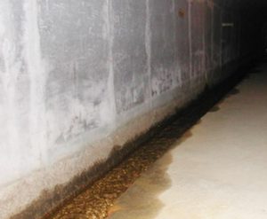
Seepage/Leakage: Seepage may be caused through contraction joint, improper lift joints and cracks. Uncontrolled seepage may further cause leaching, piping and build-up of internal pressure, which may lead to sliding or overturning.
Prominent examples of adverse effects of seepage/leakage on concrete/rubble concrete dams are: In Maharashtra, Koyna dam; in Andhra Pradesh, Nagarjuna Sagar; in Kerala, Periyar dam, and the affected masonry dams are: In Rajasthan, Parbati dam; in Madhya Pradesh, Tigra dam, Bargi dam and Barna dam.
Chlorides: The chief cause of damage by chloride is the corrosion (the reaction of a metal with its environment) of steel in the reinforced concrete, leading to cracking and spalling of the concrete cover. In electrochemical corrosion, metals take part in chemical reaction in solution under the influence of self-induced current. Electrical potential develops when iron/metal is in contact with an electrolyte; the electric current passes due to this potential but the corrosive reaction takes place when oxygen is available at the cathode.
Anodic reaction: Fe —> Fe++ + 2 e–
Cathodic reaction: O2 + 2H2O + 4 e > 4(OH)–
It is believed that a passivating film of Fe(OH)2 or lime rich iron oxide complex is formed by the reaction of Fe(OH)2 with highly alkaline pore water (pH 12.5). Even in presence of oxygen, the film protects the metal against corrosion so long as high pH value is maintained. However, presence of chloride ions in pore fluid accelerates corrosion in concrete in several ways, which are:
- They increase conductivity and hence, the activity of the corrosion cell.
- They can reduce the alkalinity of the pore fluid to a level, which allows break down of protective film and hence, allows corrosion to proceed.
On hydration of cement, 90% of the chloride reacts with aluminates and ferrites to give solid tricalcium chloroaluminate and tetra calcium chloroferrite. Thus, only 10% of the chloride, which remains in the pore fluid of concrete and chloride present in aggregate interstices is responsible for corrosion.
Nature Fury
It includes, earthquake induced motion of the impounded water, deformability of foundation rock and interaction of motion of water, foundation rock and dam body. Dams with a height of 100 m or more show some amount of induced seismicity. Induced seismicity may be caused by superimposed water weight, reduction of frictional resistance in underlying rock due to pore pressure and decline in rock strength due to chemical alteration.
Alkali Aggregate Reaction
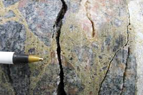
Alkali-aggregate reaction is a chemical reaction between certain type of aggregates and hydroxyl ions (OH–) associated with alkalis (Sodium Oxide and Potassium Oxide) in the cement. Usually, the alkalis originate from the Portland cement, but they may also appear from other ingredients in the concrete or from the environment. Under some conditions, the reaction may result in damaging the expansion and cracking of the concrete. Concrete deterioration caused by alkali-aggregate reaction is generally slow, but progressive; map like cracking due to alkali aggregate reaction generally becomes visible when concrete is 5 to 10 years old. The cracks facilitate the entry of de-icing salt solutions that may cause corrosion of the reinforcing steel, thereby accelerating deterioration and weakening the structure.
This alkali-aggregate reaction has two forms:
- Alkali-silica reaction (ASR): Alkali reaction with amorphous silica.
- Alkali-carbonate reaction (ACR): Alkali reaction with dolomitic carbonates. Damage to concrete from this reaction will normally only occur when all the following are present together:
- A high moisture level, within the concrete.
- Cement with high alkali, content, or another source of alkali.
- Aggregate containing an alkali reactive constituent.
- Two classic examples are Hirakud dam and Rihand dam in India
Non-Structural Cracking
Plastic Shrinkage: When the rate of evaporation of bleed water is faster than the bleeding rate, it gives rise to possibility of an effect called ‘plastic shrinkage’. The removal of water by evaporation or suction leads to a reduction in the bulk volume of the concrete and if the concrete cannot follow this change in volume fast enough, such as by settlement, it results in cracks. Plastic shrinkage cracking is most common on flat slabs placed during hot or windy weather which are not protected almost immediately after laying. A particularly severe form of plastic shrinkage cracking occurs when concrete is placed on a high suction substrate.
Drying Shrinkage: Evaporation of moisture at a rate higher than the rate at which water rises to the top is a definite cause of such shrinkage. The environment, RH, wind velocity, temperature of concrete and environment contribute to this drying out.
Thermal Cracking: The cracking occurs in the interior when the temperature rises and, on the surface, when the temperature decreases. The peak temperature rise of concrete is estimated to be around 12°C per 100 kg of cement content, in cubic metres of concrete. A maximum temperature difference of 20°C is recommended to limit the potential thermal cracking. It is therefore advisable to keep this gradient inside-outside as low as possible; this can be achieved by preventing heat loss from the surface.
 |
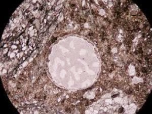 |
| Fig. 3: Alkali Aggregate Reaction (AAR) in Concrete | |
Other Causative Factors
Poor quality control during construction and fire damage (less reported) also contribute to the deterioration of concrete.
Evaluation Of Structures
The aim of performing evaluation of concrete is to identify and define the area of distress. The objectives are:
- To identify causes of distress and their sources. Systematic documentation of all observations is essential, which will greatly facilitate the diagnosis and assessment of dams;
- To assess the extent of distress occurred due to corrosion, earthquake or any other reason;
- To estimate the residual strength of the structure;
- To assess the extent of requirement of repair and/or rehabilitation. Available space and accessibility will determine the selection of the repair method and repair strategy. Also, prioritization of repairs and their sequencing are important components for deciding the repair strategy.
In-situ tests, sizeable portion of which can be non-destructive, can be performed on concrete at the site itself. The few tests performed at site can be destructive to a limited extent. Furthermore, destructive tests on concrete cores are performed only in the laboratory. The destructive and non-destructive tests provide valuable information.
Non-Destructive Tests
- Surface Hardness
- Windsor Probe test
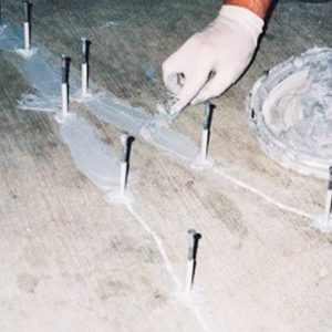
- Pull-out test
- Pull off method
- Ultrasonic Pulse Velocity
- Core test
- Ground Penetrating Radar
- Detection of Reinforcement in Reinforced Concrete Structures
- Half Cell measurements
Destructive Tests
- Core recovery
- Compressive, pulse wave velocity and other non-invasive tests
- Carbonation test
- pH value of concrete
- Chloride ion content
- Mineralogical tests
- Any other chemical tests as per requirement
Repair Materials/Techniques
Various repair materials have been adopted in the past to rehabilitate concrete structures. The suitability of a material depends on the type and extent of repair, cause of damage, type of structure, economy and availability of materials, etc. Some of the promising repair materials/techniques are mentioned below briefly.
Grouting
Cement grouting is suitable for cracks more than 0.25 mm wide. For cracks finer that 0.25 mm, superfine cement grouting or chemical grouting is suitable. Polyurethane, epoxy and other polymeric compounds are used for grouting cracked concrete.
 |
High Strength Concrete (HSC) Roller Compacted Concrete (RCC) |
Moreover, in this method, large volume of cement can be replaced with mineral admixture like fly ash. The saving in cement and utilization of waste disposal (fly ash) therefore makes RCC environment friendly and economical.Apart from new constructions, RCC is also suitable for enhancement of spillway capacity, design flood, and construction of impermeable upstream barrier in existing masonry/earth dams. It has been effectively used for enhancing reservoir capacity, improving safety of existing dams against earthquake, overtopping, etc.
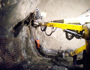
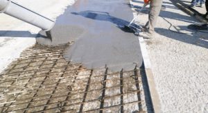
Fibre Reinforced Concrete/Shotcrete
Fibre-reinforced shotcrete, as per the report of ACI Committee 506-1R, is defined as mortar or concrete containing discontinuous discrete fibres that are pneumatically projected on to a surface at a high velocity. The fibres for shotcrete can be made of steel, glass, synthetic and natural materials. In shotcrete, for structural and non-
structural purposes, steel fibre is preferred. Recently, synthetic fibres have also been effectively used for underground applications. Further, when the fibres are made of steel, the material is called steel fibre reinforced shotcrete (SFRS). SFRS is thus essentially a conventional shotcrete to which steel fibres are added. The shotcrete may also contain pozzolana and other admixtures used with the conventional concrete.
The addition of fibres in shotcrete matrix mainly improves its toughness, impact and fatigue resistance. In dams, SFRS is effective against abrasion/cavitation erosion and impact resistance. It offers a reduced rate of damage by arresting crack propagation. However, SFRS is not so effective in low velocity water flows carrying small size pebbles.
Sprayed Concrete
The Indian Standard 9012-1978 defines sprayed concrete/shotcrete as mortar or concrete conveyed through a hose and projected on to a surface at high velocity. The sprayed concrete is highly suitable for application in restricted areas, as no form work is required in this process and it can be applied in any profile. Also, it can be used on u/s face of masonry dam to reduce seepage.
| Self-Compacting Concrete (SCC) Self-compacting concrete is the concrete that can flow under its own weight and completely fill the formwork even in the presence of dense reinforcement, without the need of any vibration whilst maintaining homogeneity (EFNARC, 2002). The use of SCC offers the benefit of the elimination of compaction work, leading to reduced cost of placement; shortening of the construction time, leading to improved productivity. SCC can be placed in a horizontal area of about 20 m diameter from single outlet without loss of homogeneity. Therefore, considerable time is saved which would otherwise be required for frequent curtailment or enlargement of outlet pipes while placing conventional concrete in large areas with pumps. A reduction in noise pollution due to elimination of vibration, improved homogeneity and excellent surface finish are other advantages of SCC. It is highly suitable to repairing congested locations. |
 |
Further, it is most suitable when delicate embedded parts are required to be protected from getting misaligned due to vibration, for example, second stage concreting in gate grooves in hydraulic structures.
Other Materials/Techniques
- Epoxy mortar/concrete
- Polymer impregnated concrete
- Polyurethane coating/neoprene paint on spillway to guard against cavitation
- Steel cladding for erosion protection
- Cable anchors to anchor dam body with foundation to counter development of tensile strength
- Geomembrane on u/s face to control seepage in RCC dams/masonry dams and protection against ASR/acids
- Chemical Rust removers for corroded reinforcement
- Passivators for reinforcement protection
- Surface coatings for protection of RCC
- Steel/concrete jacketing
- Raking and Pointing
 |
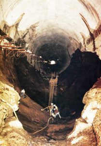
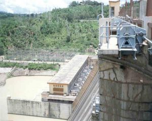
Case Studies Of Dam RepairsRihand Dam Project, Uttar Pradesh |
Within a decade of commissioning of the project, the following manifestations of structure’s distress started appearing:
In some of the machines, clearance between moving and stationary parts had gone beyond permissible limits and there was frequent tripping.
Also, problems were encountered in moving draft tube crane, sealing of intake gates, operation of stop log gates, spillway and passenger lift.
- Map like cracks were witnessed at various locations.
- High level technical experts committee set up in 1985 for safety of the dam observed that the development of cracks in the concrete were solely due to the onset of alkali-aggregate reaction (AAR). The remedial measures suggested by the committee were implemented. The measures were:
- Closing of emergency passenger lift located in shaft of the block 34 at RL 830 ft
- Rehabilitated of the penstock gallery columns showing distress by epoxy grouting and steel jacketing.
- Treatment of cracks using epoxy
- The treatment of the cracks is being followed by regular monitoring of cracks using 2D and 3D crack monitors.
 |
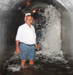
Kadamparai Project, Tamil Nadu |
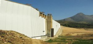
After a detailed study, it was decided to dewater the dam first. Thus, the lake water was stored in Lower Aliyar project and the u/s face and the inside portion of the dam was fully treated by grouting and standard measure. Thereafter, the dam was carpeted on the u/s face with geomembranes as per details given below:
- First Layer – Geotextile 1 cm thick (to provide mobility to seepage water, if any)
- Second Layer – 3-4 mm thick impervious geo composite (geomembrane + geotextile)
Moreover, seepage measuring sensors were placed at appropriate locations during the carpeting exercise. The seepage condition before repairs was 38,000 l/min, whereas post the repair, seepage in the entire dam body mass was 60 l/min. The dam has been functioning without any hindrance since 2005. The total cost of the project was Rs. 12 Crores with a warranty of 10 years.
 Repair Dewatering |
 Geocomposite (geomembrane with a layer of geotextile) |
|
 Geomembrane (impervious barrier) |
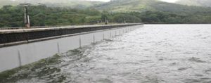 after Carpeting |
 |
Conclusion
The responsibility of undertaking the repair and rehabilitation of a structure lies with the owner. Therefore, it becomes incumbent upon the owner to assess the repair/rehabilitation needs using modern tools. Once done, cost-effective solutions are to be applied diligently to enable the structure to serve its intended purpose and lower the risk of failure considerably.
References
- Aboutaha, R. S., & Jirsa, J. O. (1996). Steel jackets for seismic strengthening of concrete columns. In Proceedings of the 11th World Conference on Earthquake Engineering.
- CSMRS Report on testing of Epoxy Concrete Mixes for Singur Dam, AP
- Ghobarah, A., Aziz, T. S., & Biddah, A. (1996). Rehabilitation of reinforced concrete beam-column joints. In Eleventh world conference on earthquake engineering, Mexico.
- Guerrero, J. J., Gomez, B., & Gonzalez, O. M. (1996). Jacketing of reinforced concrete members. In World conference on earthquake engineering. Elsevier Science Ltd.
- Metcalf, M., Dolen, T.P., & Hendricks, P.A. (1992). Santa Cruz Dam Modification. Proceedings of Conference sponsored by ASCE, Roller Compacted Concrete III, Edited by K.D. Hansen and F.G.Mclean.
- ACI MNL-3(16) Guide to the Code for Assessment, Repair, and Rehabilitation of Existing Concrete Buildings.
- ACI 207.6R-17: Report on the Erosion of Concrete in Hydraulic Structures.
- ACI 364.1R-19: Guide for Assessment of Concrete Structures Before Rehabilitation.
- ICOLD Bulletin – 165 Selection of Materials For Concrete In Dams
- ICOLD Bulletin 135, 2010 Geomembrane sealing systems for Dams.
- ICOLD Bulletin 119, 2000Rehabilitation of dams and appurtenant works – State of the art and case histories. State of the art and case histories
- ICOLD Bulletin 107, 1997 Concrete dams – Control and treatment of cracks.
- Control and treatment of cracks
- ICOLD Bulletin 79, 1991 Alkali-aggregate reaction in concrete dams – Review and recommendations. Review and recommendation
- ICOLD Bulletin 71, 1989 Exposure of dam concrete to special aggressive waters-Guidelines