 |
Mr. KVB Reddy MD & CEO, L&T Metro Rail (Hyderabad) Limited Hyderabad |
Hyderabad Metro Rail is a Public-Private-Partnership Project, that is being implemented through a special purpose vehicle (SPV) – “L&T Metro Rail (Hyderabad) Limited” – part of L&T Group Company. It is being executed on a design, build, finance, operate and transfer (DBFOT) basis with an investment in excess of Rs.16,000cr, generating a 10,000 plus -direct employment during construction period, and 3,000 post commissioning. Indirect employment to vendors and others are around 5,000 during construction period and around 100000 after commissioning including the18.5 million sft of Transit Oriented Development. The concession period for the project is initially for 35years, which is extendable further by 25 years.
The Hyderabad Metro Rail Network covers a total distance of 71.16km and the Metro includes ultra-modern stations with state-of-the-art depots and complete infrastructure. L&T Metro has engaged world-class consultants, reputed contractors / vendors for construction of various Metro systems.
This project also has an opportunity of 18.5 million square feet of Transit- Oriented Development (TOD) in the earmarked (P&C) areas and depots.
- Traffic Studies conducted by L&T Ramboll
- Benchmarked against independent Traffic studies of other consultants
- Parking & Circulation Area (6mn Sq. ft.), Depots (12.5 mn Sq. ft.) & Retail area in stations (20% of floor area of each Station)
- M/s Mckinsey commissioned has undertaken a value enhancement study for TOD
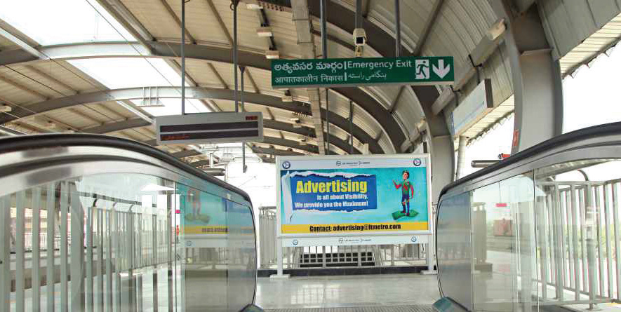
- Advertisements – at stations, viaduct, in train, co-branding etc.
- Parking – Provided at parking and circulation areas and depots
Specialty of the Project
Some “Firsts” in this Project are highlighted below:
- Largest Metro Project in the world to be developed in PPP format
- First Integrated Metro + Transit Oriented Development Project = Seamless Commute.
- It is also the largest Single Urban Development Project in India
- This project is being implemented not as a simple mass transit system, but as an Urban Redesign Concept with emphasis on last mile connectivity, room for cycling and other non-motorized transport, pedestrian facilities, green areas and public spaces with an eye on aesthetics
- The Government is taking initiatives to make this project as a model for multi-modal interchanges
- Financial closure achieved within 180 days of signing the concessionaire agreement
- All the 3 main rail terminals, 8 important Bus depots / stations, and 6 MMTS (Local rail) stations are being integrated with the Metro Rail
- Communication Based Train Control System is first time introduced in Indian Metro rail system as a signalling system, which can accommodate much greater frequency of train traffic
- Innovative design for Stations – Spine & Wing arrangement – This reduces the land acquisition / property clearance near stations
- Operator in place at a very early stage; O&M inputs into Project System design
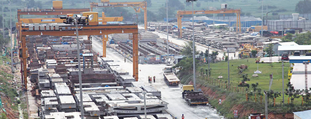
- 2 Largest Pre-cast yards in urban areas
- Section of 30km inaugurated by Hon’ble Prime Minister of India on 28th November 2017. Operations underway since then.
- Work in full swing on the remaining stretches to complete the same soon.
Substructure & Foundations
- Piers are columns, which provide vertical support to the viaducts
- Square or rectangular piers used with pier cap flares of required width at the top.
- Foundations: majority of foundations are shallow open foundation with CLSM (Controlled low strength material) cast below foundation raft in case of inadequate bearing capacity of soil at 2.5 m level BGL (below ground level). In other cases, pile foundations of end bearing type with pile diameter ranging from 800 mm to 1000 mm have been used.

Bearings
These are the elements, which take the axial loads of the viaducts and all the equipment above it. Generally, neoprene bearings in combination with seismic arrestors are used to take care of all the vibrations. For special/obligatory span POT/PTFE and spherical knuckle bearings are used. Special stability checks carried out on superstructures for sharp curves (Min Radii of Curvature 128 m).
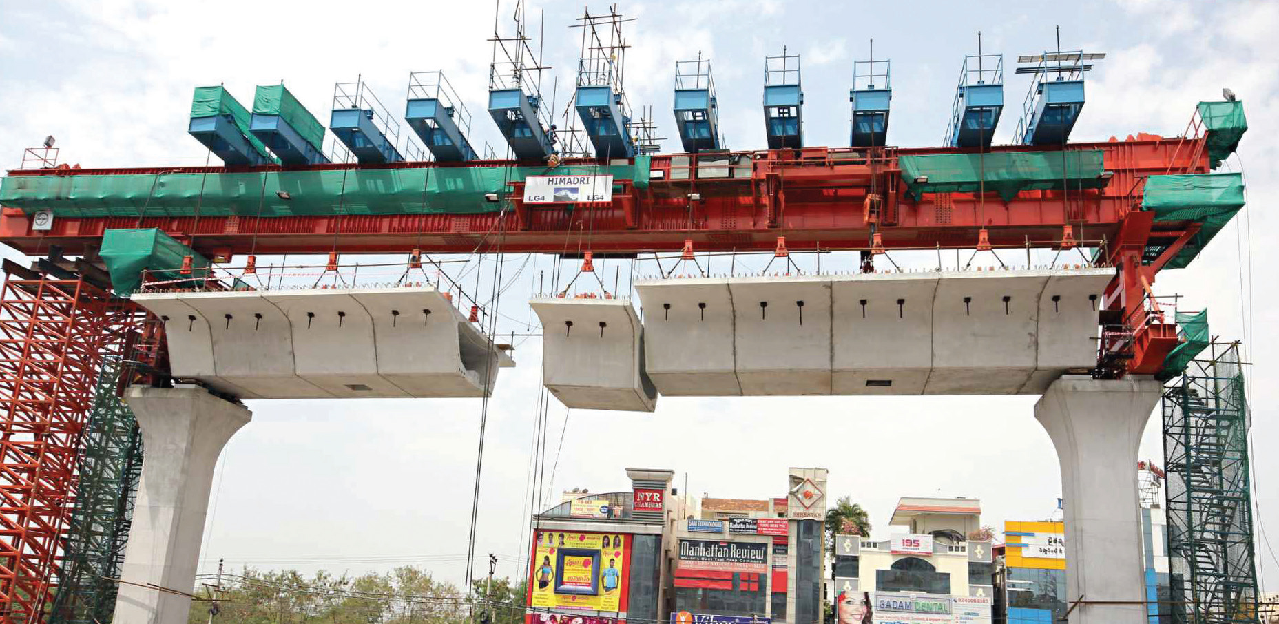
Viaducts/Superstructures
Viaducts are horizontal platforms over which the train runs. These viaducts are basically segmental precast post-tensioned box girders joined to span between two piers with the help of launching girders. Special/obligatory spans are either cast-in-situ or precast (3-span continuous or simply supported). The viaducts are accompanied by RCC parapets on top to support the signalling equipment and overhead masts. Noise barriers are provided on parapets in sensitive areas. The entire structure has a Design basis report (DBR), which was prepared with the knowledge of all stakeholders and has been RDSO/MoR approved.
Railway over Bridge (ROB)
There are 8 ROBs where Metro viaducts will be crossing the Indian Railways lines. The ROB structures are being designed by M/s Ramboll as Detailed Design Consultants (DDC), checked and approved by M/s Aecom – Feedback Infra on behalf of LTMRHL, approved by independent engineer (I.E) M/s Louis Berger Company on behalf of HMRL and finally proof checked by RITES on behalf of South Central Railways.
Oliphenta RoB
Amongst all the 8 Metro RoBs, Oliphenta Bridge construction is the toughest and an engineering feat.
- It is located next to the Secunderabad Railway station, which is a very busy station and works round the clock
- Since this is a double elevation RoB over an already existing elevated RoB, with a view to accommodate the future double-decker trains of Indian Railways, it is being built at a height of about 60 feet from road level.
- It has the longest obligatory (main) span of 272 feet to accommodate the 8 existing and 5 future railway tracks. This means this Metro RoB is being built at a height of 60feet and without any middle support for 272 feet.
- As the Metro alignment is in a steep curvature coming from Mettuguda side (a curve of 128m radius), the width of the steel bridge had to be increased to accommodate the Metro tracks with steep curvature.
- The entire steel bridge weighing about 1100 tons made of special high-grade steel was first manufactured and assembled at a factory in Ghaziabad (near Delhi) simulating the site conditions of Oliphenta location and later dismantled piece by piece and brought to Secunderabad for reassembling.
- The high strength steel truss structure elements are joined together with the support of these steel plates by using HSFG (High Strength Friction Grip) bolts. The assembling of these elements with absolute precision has been done on a one-acre site of railways near Oliphenta temporarily taken on lease.
- This precision bolting and welding at a height of 60 feet at the bottom level of the bridge and at about 90 feet (top level of the bridge) can be done only by specialized workers under the supervision of bridge engineering experts. Since conventional bridge bearings cannot take care of the large longitudinal and lateral forces induced by a large span bridge, special “spherical bearings” which are the latest in bridge engineering are being used.
- The total number of HSFG bolts used are about 65,000 and they are supported by Direct Tension Indicator (DTI) washers for splicing (bonding) the joints.

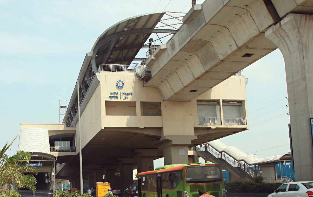
Station Design
Balanced cantilever structural system adopted for metro stations, is a unique one. It provides several advantages to the city during construction as well as after construction. Each station is having three levels, The Street Level, the Concourse Level and the Platform Level.
Concourse level is made up of pre-cast segmental post tensioned spine girder with end segments supported on bearings placed over pier cap. Precast post tensioned wings are attached on either side of the spine girder ensuring the service requirements.
Platform structure comprises of cast-in-situ slab laid over longitudinal precast pre-tensioned secondary beams. These secondary beams supported on cast-in-situ post tensioned concrete arms as primary beams. Roof is supported by a portal frame steel structure with metallic corrugated sheet.
The station pier in the road median is designed to support the track structure, platform structure and concourse level structure. The station piers are located at the central median of road and the station is cantilevered on the single pier, thereby avoiding any structural support from the shoulders of the road. The station box is proportioned to suit even for narrow streets of the city. Pier centres (spans) are maintained in such a way to achieve necessary road clearance (5.5m) and to meet the rail level requirements while carrying the station and viaduct loads. Each span between any two piers are independent and kept separate by providing expansion joints.
Entry-exit structures are located on either end of the road to facilitate easy approach for the passengers. Stations are designed considering the evacuation criteria prescribed as per NFPA 130 standard and barrier free design. All relevant standards such as BIS, IRS-CBC and BS codes have been adopted.
The Indian Green Building Council (IGBC) has launched IGBC Green Mass Rapid Transit System (MRTS) rating, to encourage green concepts in the design, construction & operation of all new Rail based MRTS projects. The rating system helps to address national priorities like conserving natural resources, demand side energy & water efficiency, adoption of renewable energy, management of waste and commuter health & comfort.
Stage I &II of L&T Metro Rail (Hyderabad) Limited has been awarded with the prestigious IGBC Platinum Rating for its 17 elevated stations, the highest accomplishment for any project. LTMRHL’s technical innovations of adoption of the spine & wing concept, the hump at the station platform level, regenerative braking in rolling stocks and greening of median areas below viaduct has led to the spread and growth of green metro rail movement in the country. LTMRHL will be the trendsetter for the upcoming metro rail projects all over India to incorporate some of the initiatives.
Concrete Used
- Temperature controlled concrete was used in all the structures. The automatic concrete batching plants were connected to chilling plants, which cool down water to a temperature of 50°C. The concrete was transported via transit mixers which were wrapped with multi- layered hessian cloths to keep the drum cooled, during the transit.
- Concrete laying was predominantly done during the night hours, to protect from hot weather and avoid probable plastic shrinkage cracks.
- The mix design of concrete was carried out to achieve a higher workability of 200±25mm by slump test at the placing location without any bleeding and segregation. Poly carboxylate based chemical admixtures were used for this purpose. These admixtures have been blended to retain the workability up to five hours.
Construction Practices
- The segments and the beams are being precast in a yard. The precast yard is located at Uppal, equipped with overhead gantries and plant for readymade reinforcement steel. The precast yard is bifurcated into many smaller units, called as ‘reinforcement yard’, ‘casting yard’, ‘curing yard’ and ‘stacking yard’.
- Standard formwork was fabricated with steel. The bed that receives the segment precast was survey checked and adjusted to alignment and profile of the station. Reinforcement was tied on a standard zig, lifted and placed on the above bed. The side shutters and inside forms were placed, HDPE sheaths were placed and aligned, and the mould is ready to receive the concrete.
- Concrete in the segment/beam mould was placed in two methods, one by ‘boom placer’ and the other by the ‘concrete crane bucket’ hung through gantries.
- ‘Concrete Boom Placers’ were used to place the concrete at its position. These were helping not only to reach higher heights but minimize segregation of mix even at longer travels and/or higher reaches. The concrete in the piers was placed by tremie method to avoid segregation due to higher height of fall.
- The concrete in pier was compacted using high frequency vibrators with longer trunks/cables. Mould vibrators were also used for precast segments.
- The precast girders/segments/wings are transported using long body trailers and erected in situ using the launching gantries. Each span receives 8-10 of the precast segments based on the span configuration (13m or 17m). After completion of post-tensioning activity joining the segments in a span, the span lowered on to the elastomeric bearing placed atop the pier cap.
- The precast pre-tensioned beams meant for the platform, transported using trailers, are erected insitu using crawler mounted cranes or chariot cranes installed on the rail track on viaduct. Each span receives three beams on each side of Left Hand Side and Right- Hand Side platforms.
- The Entry-Exit to Station on all its four ends/sides, Underground sumps, Escalator and Lift supporting structure, Staircases made of reinforcement concrete are cast-in situ as per approved ‘Good for Construction (GPC)’ drawings.
Special Machineries
Apart from using Launching Girders/Gantries, ‘Chariot Crane’ has been used. Chariot Crane is a 75MT crane on steel wheels. Above the plinth beam that is meant for installing rails for train to move, temporary rails have been installed and chariot crane deployed. This crane was used for erection of pre-cast pre-tensioned beams for `station platform.
Safety Practices
- Introduced Designer’s certification of temporary structures prior to loading/use, to conform formwork standards as per the scheme requirements.
- New colour coding of helmets was introduced to newly joined employees. This will enable easy identification of new employee till he/she gets familiar with the system, guided/supported by the senior employees, to prevent unsafe acts.
- Height pass was introduced to all the people involved in working at height, to familiarize with dos and don’ts.
- Introduced modular frames instead of guard rail at platform level to prevent fall of material.
- Introduction of rear cameras to tele-handlers for effective reversing of vehicle, targeting zero harm.
- Introduction of blue-tooth ear-in speakers to all operators/ drivers to stay focused while driving
External Station Structure
The balanced cantilever structural system typically adopted for metro stations is a unique one. It provides several advantages to the city during as well as after construction. The station piers are located at the central median and the station is cantilevered on the single column, thereby avoiding any structural support at the side medians. Following advantages are achieved by this system:
- Sleek station box (20m) suitable for narrow streets of the city
- No obstruction to the surrounding properties
- Minimum impact on site lines for branching bye-lanes and roads
- No tunnel effect i.e. adequate ventilation and lighting for road users below
- Delinking of station box construction with entry structure construction
Passenger Safety
The stations are designed to meet evacuation and fire separation norms as per internationally accepted standard for Fixed Guide Way Transit and Passenger Rail System, National Fire Prevention Association (NFPA-130). Fire detection and suppression provisions are planned in accordance with Indian National Building Code. Essential power back-up is provided for operational purposes as per relevant codes.
Differently-abled Friendly
Ticket vending machines are provided to aid the passengers with speech impairments. Wide automatic fare gates are provided for passengers on wheelchair. Direction to all commuter facilities like ticketing, washroom, lifts, staircase, train door, customer service, etc. has been provided through tactile flooring for visually impaired passengers. There are designated wheelchair spaces in the first and last car of the trains. Five per cent of seats are designated for the physically challenged passengers. Fixed and dynamic lit signages within the trains are provided to guide hearing impaired passengers. Announcements are made in the train to aid those who might be unable to see or read the information being shown on the signage.
Eco-friendly
Energy efficient features are incorporated in station design. The stations are generally located on hump which means reduced power requirement to decelerate or accelerate for an approaching or departing train respectively. The stations are open buildings with minimum external walls in public areas, reducing lighting requirements during day time and providing ample ventilation. LED lighting systems with reduced power requirements and solar panels to capture alternative power, etc are installed in the station.
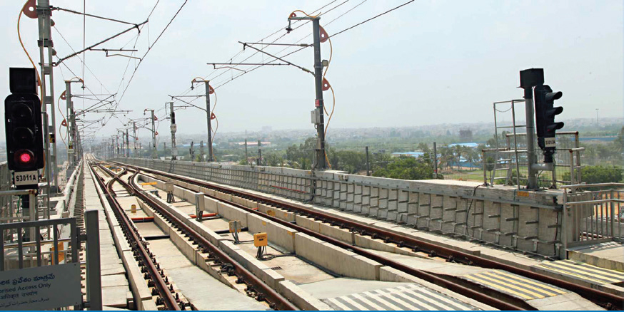
Trackwork
The entire mainline of The Metro Project has ballast-less track, whereas tracks in depots are ballasted and special tracks. The primary reason of adopting ballast-less track technology is lower maintenance requirement, which suits our time constraints (non-revenue hours available for maintenance work). The permanent way consists of rails of profile 60 E 1 Head Hardened Gr.1080 for complete main line and rails of profile 60 E 1 Normal Rails Gr.880 for depots which shall be 18 m long. The rails manufacturing and testing will be done as per IRS – T- 12, 2009. Restraining rails of profile 33 C1, grade 880 of 13 m length shall be provided for all curves of radius less than 190 m.
Fastening system 336 is being adopted for ballast-less track in this project. The fasteners are spaced at 650mm c/c on viaduct and ramp with 1 in 40 rail inclination. The track in the depots has been laid on ballasted track and special track with Standard Gauge Mono block PSC Sleepers with the spacing at 600mm c/c sleeper using ERC MK III fastening system and GFN Liners of indigenous make and 65mm stone ballast with minimum cushion of 250mm under the sleepers. The cushion is 300mm for test track. Portion of depot track has also been laid as embedded track with special base plates and on plinth with ballast-less fastenings to suit the requirement. All the turnouts to be negotiated are with 1 in 40 rail inclination. 1 in 9 switches of radius 300 and 190 for the main line and 1 in 7 switches of radius 190 in the depot with Zu 60 profile (thick web) are used. All the running rails are continuously welded by Flash Butt Welding/Alumino Thermic Welding processes. The track on Main Line has been laid on plinth type ballast less track with rails discretely supported by ballast less fastenings on Concrete plinths of M35 grade.
Sustainability
Green construction practices have been followed such as solid waste management, rainwater harvesting, pollution control, environmental protection:
- Metro-the efficient eco-friendly time saving initiative has made luxury economical. Go-green initiatives have been the crux of the project
- Metro rail is one of the cleanest and greenest modes of transport, which helps in reducing the Green House Gas (GHG) emission and Carbon Foot Prints in the City of Hyderabad. As part of this, we have initiated ‘Clean Development Mechanism –CDM’ registration process with United Nations Framework Convention on Climate Change (UNFCCC) along with our Ministry of Environment & Forests
- We anticipate generating more than 3.5 million CERs though our project (our project is already appearing in the UNFCCC website). The carbon emission reduction will be both due to modal shift from the conventional modes of transport to metro as well as due to regenerative braking technology. The project is likely to bring a vast modal shift to metro and provide the people of Hyderabad a comfortable, air-conditioned, economical and yet green transport. Anticipated reduction of 3.5 lakh metric tons of CO2 per year from the atmosphere due to people using electrically operated trains thereby enhancing green environment.